Sensor fusion is most frequently discussed in smartphone and automotive control applications. However, the fusion aspect was initially created for military analysis. From the analysis standpoint, for improved decision-making, medical applications can and have benefited from sensor fusion. One example is in cancer detection and focused surgery. Specifically, the detection of and surgery for prostate […]
Ultrasonic
What’s the difference between sensors used in underwater, flying, and creeping robots or drones? part 3

The abilities of robots continue to advance with highly capable products performing a variety of tasks, looking almost humanlike as they speak, and even garnering appearances in movies. Perhaps less attractive but equally or even more useful, creeping or crawling robots bring drones down to earth and, in fact, inside the earth. Unlike the micro […]
SAM increases electro-mechanical sensor reliability
Electromechanical sensors, such as pressure, flow, and vacuum switches, composed of electrical and mechanical parts, interact and transmit information or commands to other components of a larger, more complex system. To keep the entire system functioning safely, sensor producers need to manufacture these devices to precisely deliver accurate measurements. Traditionally, however, if there was an […]
How are ultrasonic MEMS sensors being used for 3D obstacle detection and collision avoidance?
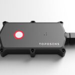
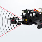
In addition to radar, LiDAR and camera sensing used in 3D obstacle detection and collision avoidance in advanced driver assistance systems (ADAS) in vehicles, ultrasonic sensing has been used as well. Traditionally, the ultrasonic sensors used transducer-based technology to provide a microphone to transmit and receive the ultrasonic signal in passenger vehicle parking applications. Using Infineon’s […]
How do time-of-flight sensors work?
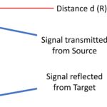
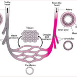
Using the time-of-flight (ToF) principle, a ToF sensor measures the distance between the sensor and an object. The sensor emits a signal that is reflected off an object and then detects the time for a round trip to occur. Typically, either light or sound waves can provide the transmitted signal. In either case, the distance […]
How to design an effective telehealth system

By Marcel Consée, Mouser Electronics Healthcare can be deeply personal, and direct contact between patients and medical personnel remains vital. However, taking the relationship between doctors and nurses out of the equation can sometimes make sense. Medical crises such as the global COVID-19 pandemic accelerate the adoption of telehealth methods, even though the original idea […]
An introduction to ultrasonic sensors
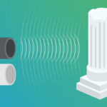
Ultrasonic sensors have been a popular method for distance measurement and object detection for many years. Their basic operating principle works by measuring the amount of time it takes for their emitted ultrasonic pulse of sound to bounce off an object and return, hence the name ultrasonic sensor. With the market for autonomous robots, vehicles, […]
Graphene-based flowmeter sensor measures nano-rate fluid flows, Part 1: The challenge
When it comes to nearly all biological measurements, the ranges of many of the parameters of interest are orders-of-magnitude below those with which many engineers are familiar. Instead of megahertz or even kilohertz, the living-creature world is in the single or double-digit hertz range, such as the roughly 60+ beats per minute (BPM) for a […]
The working principle, applications and limitations of ultrasonic sensors
The ultrasonic sensor (or transducer) works on the same principles as a radar system. An ultrasonic sensor can convert electrical energy into acoustic waves and vice versa. The acoustic wave signal is an ultrasonic wave traveling at a frequency above 18kHz. The famous HC SR04 ultrasonic sensor generates ultrasonic waves at 40kHz frequency. Typically, a […]
The next level of ultrasonic technology from Pepperl+Fuchs
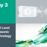
Ultrasonic sensors have rapidly gained popularity in recent years—what was once a niche product has now become a key technology that can be found almost everywhere in the automation sector. As the market leader in this sector, Pepperl+Fuchs will be dedicating a whole day of events at its second Online Summit to providing insight into the […]