Wind turbines are very complex machines. It takes a lot of sensors to ensure their continuous operation generating green energy. This FAQ reviews some of the sensors used to monitor wind turbine operations, such as: Eddy current sensors monitor the lubricating gap of the shaft, how the turbine shaft rotates both axially and radially inside its housing and turning stresses experienced by the nacelle; Displacement sensors that monitor structural integrity of towers and nacelles; Accelerometers that measure tower sway, nacelle rotation, and gearbox vibrations; Optical fiber Bragg grating sensors that enable individual pitch control of the blades, and; Mechanical, ultrasonic and LiDAR wind sensors that monitor and predict wind speeds.
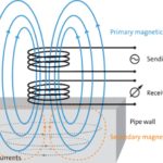
Eddy current sensors, also called Foucault currents, are used to measure the lubricating gap of the shaft. These sensors are environmentally rugged and can operate when immersed in oil at high pressure and temperatures. The gearbox and generator have an ‘elastic’ bearing to handle the large mechanical loads they experience. The couplings in wind turbines must balance the different movements of the gearbox and generator. The ‘elastic’ nature of the bearings is called run-out and enables the shaft to vary its rotation both axially and radially inside its housing. Acceptable runout is precisely specified in wind turbines. Eddy current sensors can monitor even minute changes in runout, enabling preventative maintenance before damage or a catastrophic failure occurs.
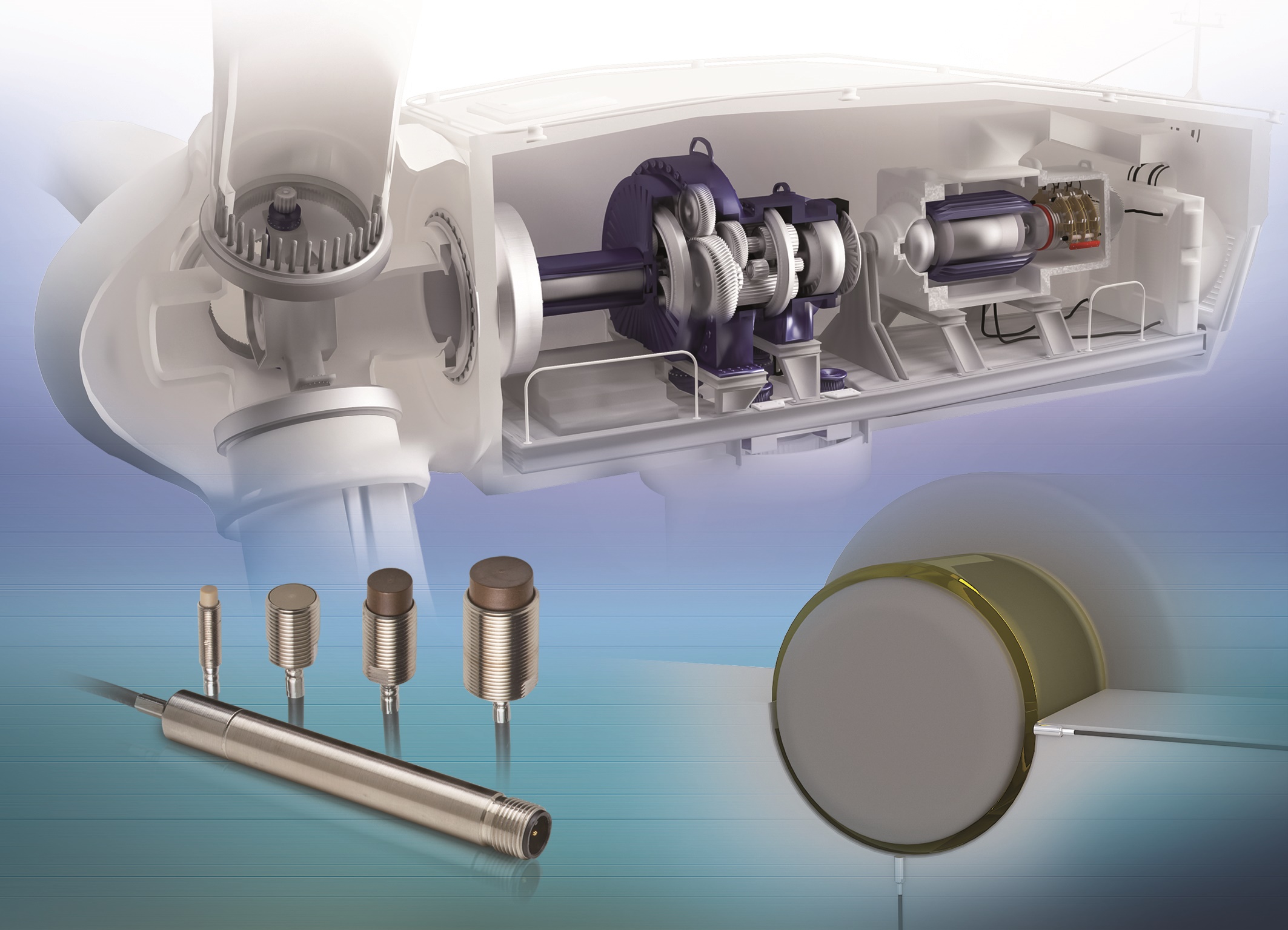
Eddy current sensors also measure the turning stresses caused by vibration, wind loads, and other factors experienced by the nacelle that can lead to structural problems. And they are used to monitor the axial, radial, and tangential deflection of the clutch disks to ensure that the rotor can be safely stopped during high winds. Some eddy current sensors are temperature compensated to operate reliably in conditions of large fluctuations in ambient temperatures. They provide a higher bandwidth compared with alternative sensor technologies and are suited to provide precision measurement of high-speed movements (Figure 1).
Displacement sensors
A variety of displacement sensor technologies are used to monitor structural integrity. Laser displacement sensors can measure small movements in the tower relative to the base and monitor the structural integrity of the installation. A laser displacement sensor sends a laser beam to a receiver some distance away and measures any change in the alignment between the two. These sensors are very accurate, enabling trend data to monitor if a problem is emerging and how rapidly it is developing.
Capacitive displacement sensors can measure the generator air gap (distance between the rotor and stator) in the turbine. Changes in the generator air gap result in changes in capacitance and these sensors can operate in high electromagnetic fields and at high temperatures.
Draw-wire displacement sensors can measure airflow by detecting changes in the position of air flaps. These sensors consist of a spring-loaded wire wound onto a spool-shaped transducer. As the wire extends or retracts, the spool rotates and that rotation is converted to a distance measurement.
Accelerometers
Accelerometers are another type of sensor used to monitor vibration within main, yaw, and slew bearings, as well as other rotating components such as the main generator output shafts. The collected vibration data can monitor changes over time and predict impending failures. MEMS accelerometers that combine a high degree of ruggedness with high sensitivity and stability of measurements are often used in wind turbines.
Bearing wear can result in accelerometer measurement changes between 0.1 and 1.0 g. Maintenance is usually required at 1.0 g. monitoring the trend from 0.1 and upwards enables the scheduling of preventative maintenance. High-frequency monitoring is needed to identify potential bearing faults. The g force measured is proportional to the square of the frequency, and a small fault displacement at high frequencies results in a higher g force compared with the same fault displacement at lower frequencies. Accelerometers with a measurement range up to 200 g and 10 kHz are generally used in wind turbine applications. In addition, they need to survive high shock levels resulting from abrupt braking or structural impacts.
Predicting gearbox failures
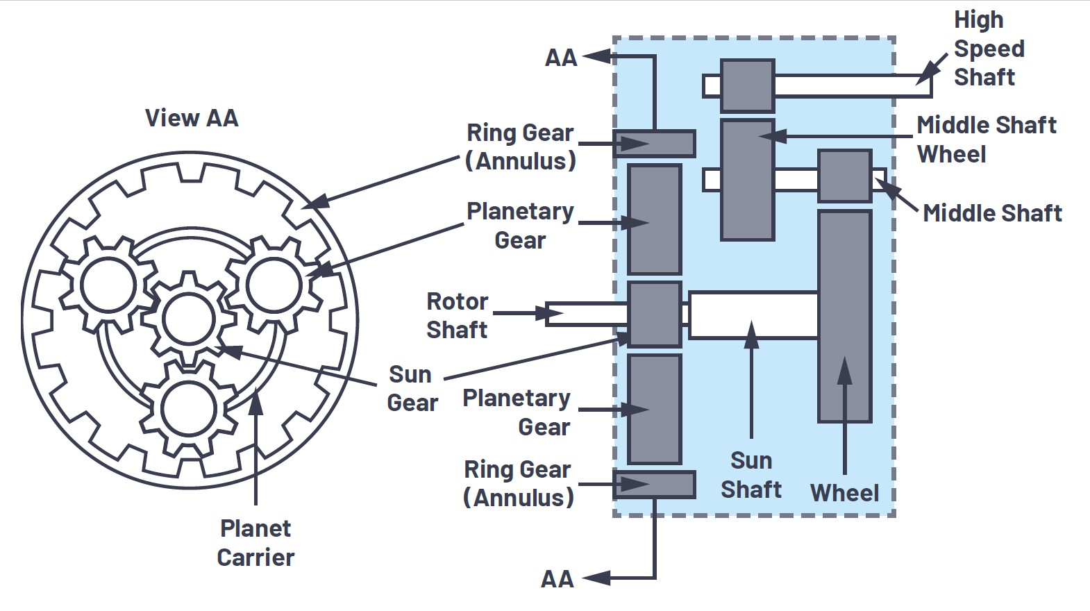
Gearboxes, rotor blades, and the generator have the highest failure rates of all wind turbine components, and the gearboxes are the worst of all. The gearbox is subjected to large mechanical stresses from changes in wind speed and braking, as well as stresses involved in transferring mechanical energy from the rotor hub that rotates at low speed (20 rpm or less) to the generator that rotates at high speed (3,200 rpm) (Figure 2).
Gearbox vibration signals need to be captured down to 0.1 Hz to meet wind turbine design guidelines. The noise floor needs to be low so that early-stage bearing faults with low vibration amplitudes can be accurately detected. In addition, to provide the necessary bandwidth to measure the harmonics of impending failures, vibration sensors rated for 10 kHz or higher are needed on both the high-speed and low-speed shafts.
Optical fiber Bragg grating sensors
With larger diameters of turbine blades, the difference in wind speed at the top and bottom of the rotors (wind shear) can be considerable. Large amounts of wind shear can result in rotor imbalances that stress drivetrain components such as the gearbox and reduces power conversion efficiency. Individual pitch control (IPC) of the blades can resolve the challenges introduced by wind shear, improving efficiency, extending gearbox life, and lowering maintenance costs.
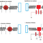
When a broadband light beam is transmitted in an optical fiber, fiber Bragg gratings reflect only a specific wavelength (the Bragg wavelength) while transmitting all other wavelengths. This reflected wavelength changes with variations in parameters such as strain, vibration, acceleration, and optical fiber temperature (Figure 3).

Figure 3: Fiber optic Bragg grating sensors experience changes in optical properties when subjected to strain and are used to implement IPC of turbine blades. (Image: Eon Photonics)
Load data for each blade must be monitored in real-time at high speed to implement an effective IPC algorithm. Electronic sensors are not suited to the task due to the frequency of lightning strikes experienced by turbine blades. Optical fiber Bragg grating sensors are insensitive to lightning strikes and have become the industry standard for blade monitoring systems.
LiDAR Anticipates Changing Winds
Conventional wind turbines use mechanical or ultrasonic feedback methods to react to wind disturbances and minimize the impact of changing winds after the fact. LiDAR sensors offer a means to anticipate changes in the wind, provide additional inputs to the wind turbine controller, and enable new control algorithms.
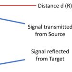
Two types of LiDAR use different methods to calculate wind speed. Continuous-wave LiDAR uses a laser beam focused at a specific distance away from the tower (Figure 5). Pulsed LiDAR uses a timing-based method that looks for the reflected laser light at different time delays, enabling it to measure the wind speed at different distances away from the tower.

There are additional variables to consider when using LiDAR wind measurement systems. For example, a wider cone angle is better at measuring wind direction but suffers from reduced wind speed estimation accuracy. Or the LiDAR can be mounted in the turbine’s hub, resulting in a measurement that is rotating at the same speed as the rotor and has a higher correlation with the wind as experienced by the blades.
When used during construction, LiDAR measurements can help to refine turbine design in such a way to mitigate against extreme events and improve the efficiency of energy production during normal operation, improving operational reliability. In addition, LiDAR measurements are sometimes done as part of the commissioning of a wind farm to compare actual wind conditions versus the specified power curve of the turbine to identify the possibility of underperformance. In some instances, LiDAR measurements can result in turbines being equipped with larger rotors to improve energy generation, or lighter weight towers can be used to reduce installation costs.
Summary
It takes a wide range of sensor technologies and hundreds of sensors to monitor wind turbine operation and ensure reliable and efficient production of green energy. This FAQ has reviewed some of the major sensor modalities required for wind turbine operation including many incumbent sensor technologies and emerging LiDAR sensors for predicting changes in wind speed.
References
Choosing the Best Vibration Sensor for Wind Turbine Condition Monitoring, Analog Devices
Fiber Bragg Grating Sensors, Eon Photonics
Lidar-Enhanced Wind Turbine Control: Past, Present, and Future, National Renewable Energy Laboratory
Sensor Fusion and State Estimation of IoT Enabled Wind Energy Conversion System, MDPI sensors
Sensor solutions for predictive maintenance of wind turbines and generators, Micro-Epsilon