Designers who use inductive proximity sensors have a choice of high-performance signal-conditioning interface ICs, each offering different sets of features, functions, and capabilities.
The first part of this article discussed some of the sensing opportunities and looked at an IC from Texas Instruments. This part looks at ICs from Renesas and Microchip Technology.
Renesas IPS2550 Inductive Position Sensor
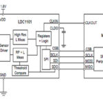
The IPS2550 operates at rotation speeds up to 600,000 RPM (relating to coil designs using one period per turn). Its ultra-low propagation delay of 4 μsec supports dynamic control for fast-spinning motors (Figure 1).
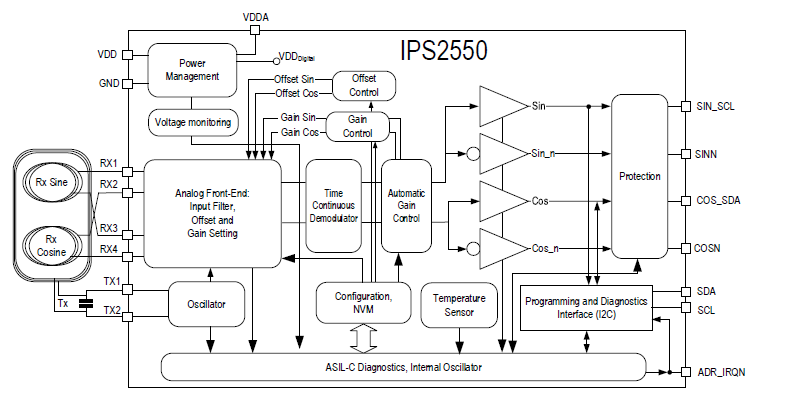
It provides two independent output interfaces:
- A high-speed analog or digital interface provides position information in demodulated analog sine/cosine raw data or digital incremental outputs (Figure 2).
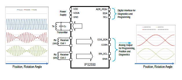
- An I2C digital interface for diagnostics and programming.
The LC oscillator generates the RF magnetic field for the sensor and operates in the open frequency band of 1.73 MHz to 5.8 MHz, which is between the short-wave (SW) and medium-wave MW) radio bands. The specific frequency is adjusted by external components, with the transmitter coil as the inductance (L) and an(external capacitor (C). The coil drive current is user-programmable.
In an embedded connection, both the sensor and microcontroller (MCU) are mounted on the same printed circuit board (PCB). In these applications, the number of connections between the two chips is not critical, so the associated microcontroller can take advantage of the separate I2C interface to constantly monitor the diagnostic registers without interrupting the analog signal flow or to change offset or gains on-the-fly.
In contrast, in a remote application, the sensor module is separate from the ECU and connected by a cable. To minimize cost, the number of wires on the cable and the number of connector pins is kept as small as possible, typically with four wires (VDD, GND, Sine, Cosine) for single-ended configuration and six wires (VDD, GND, Sine, Inverted Sine, Cosine, Inverted Cosine) for differential configuration.
As this part is targeted at critical automotive functions, it has been developed according to ISO26262 as a “Safety Element out of Context” (SEooC) device for implementation in safety-relevant systems up to ASIL C for a single IC and ASIL D for dual, redundant ICs, using internal and external safety mechanisms.
[If you are familiar with ASIL, this is a nice summary from Synopsys: “ASIL refers to Automotive Safety Integrity Level. It is a risk classification system defined by the ISO 26262 standard for the functional safety of road vehicles. The standard defines functional safety as “the absence of unreasonable risk due to hazards caused by malfunctioning behavior of electrical or electronic systems.” ASILs establish safety requirements―based on the probability and acceptability of harm―for automotive components to be compliant with ISO 26262.
Further, there are four ASILs identified by ISO 26262: A, B, C, and D. ASIL A represents the lowest degree, and ASIL D represents the highest degree of automotive hazard. Systems like airbags, anti-lock brakes, and power steering require an ASIL-D grade―the highest rigor applied to safety assurance―because the risks associated with their failure are the highest. On the other end of the safety spectrum, components like rear lights require only an ASIL-A grade. Headlights and brake lights generally would be ASIL-B while cruise control would generally be ASIL-C.” You can find more details on ASIL from Synopsys here.]
Therefore, to meet the ASIL requirements, the internal safety mechanisms in the Renesas IPS2550 include the following (and there are more):
- Detection of broken or shorted receive or transmitter coils.
- Under-voltage and over-voltage detection.
- Broken-chip detection.
- Data integrity checks (ECC and parity).
- Silicon chip over-temperature detection.
- Detection of output buffer failures.
The receiver coils Rx Sine and Rx Cosine are continuously checked for open/short circuits to ground, shorts to VDD, and shorts to the opposite coil. The receiver coils can be connected in two ways:
- An ASIL C connection, which prevents a possible short-circuit of receiver coils due to a short of two neighboring pins.
- Compatibility connection provides pin-to-pin compatibility to the IPS2200, a sibling IC targeting industrial, medical, and high-end consumer applications.
For the final IC, we’ll look at an IC from Microchip Technology.
Microchip Technology LX3301A Inductive Sensor Interface IC with Embedded MCU
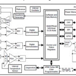
Unlike the previous two ICs, this IC also includes a microcontroller unit (MCU) and memory (Figure 3). In doing so, it allows decisions to be made at the “edge” at the sensor front end for tighter closed-loop control while eliminating the need to send “uninformative” data back to the host. It also allows for calibration and other corrections to be instituted right at the sensor.
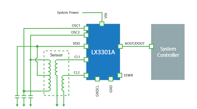
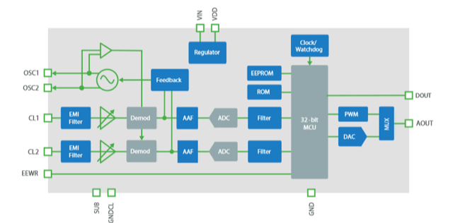
The LX3301A integrates two complete analog channels, an Internal oscillator/exciter with a frequency range of 1 to 5 MHz, 32-bit RISC processor, non-volatile configuration memory, and analog or PWM outputs into a 14-TSSOP package (Figure 4).
As with the other ICs cited here, it is designed for harsh automotive environments as well as industrial settings, so it is certified to AEC-Q100 grade 1. The device operates to its published specifications between -40 and 125⁰C and maintains its full functionality with some specification degradation to 150⁰C. It includes the required multiple-diagnostic features making it ISO 26262 and ASIL-B compliant (note that ASIL-B corresponds to the second-lowest degree of automotive hazard; the Renesas IC is rated to the higher levels of C and D depending on the configuration.)
In a typical position-sensing application, inputs from the inductive sensor are conditioned, demodulated, and converted into 13-bit values. The MCU processes these values to produce a linearized measurement value with either 12-bit accuracy (analog output) or 13-bit accuracy (PWM output). The embedded MCU and memory can handle a wide range of linearization and related issues, including a linearization algorithm with five user-defined linearization points, programmable origin, and endpoints; six segments of linearization; and programmable low- and high-plateau levels.
Conclusion
Inductive sensing is well-suited for measuring mechanical movement (linear, angular/rotation, and proximity) in automotive, industrial, aerospace, and commercial applications. It is a very viable option for rotor position sensing (especially for brushless DC motors); robotic arm positioning; fluid level sensing; proximity detection; and gear-position sensing. Along with the LVDT – its close cousin – the basic sensor offers the performance, ruggedness, and packaging these installations demand. The ICs discussed here (and others) make interfacing with the sensor at the front end and the rest of the system at the conditioned side straightforward, accurate, and precise. They also allow the designer to meet industry mandates more easily for reliability and failure-mode performance.
Related EE World Content
What are inductive proximity sensors? Part 1
What are inductive proximity sensors, Part 2
LVDT electronics, Part 1: Excitation and demodulation
LVDT electronics, Part 2: Interface circuitry
References
Texas Instrument
“LDC1101 1.8-V High-Resolution, High-Speed Inductance-to-Digital Converter” (datasheet)
“Inductive sensing: Should I measure L, RP or both?”
TIDA-00563, “Inductive Proximity Switch BoosterPack Reference Design”
Renesas Electronics
“IPS2200 Inductive Position Sensor” (datasheet)
Microchip Technology
“Robust, Low-Cost and Noise-Immune Motion-Sensing Inductive Sensors”
“LX3301A Inductive Sensor Interface IC with Embedded MCU”