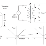
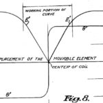
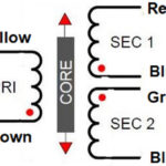
The interface electronics for the LVDT must excite the primary-side winding with a sine wave and then demodulate the two resultant secondary-side waveforms; modern ICs make this analog-signal process fairly straightforward.
Part 1 of this FAQ looked at the basics of LVDT excitation, demodulation, and waveforms. This part looks at two standard ICs which implement the LVDT signal-conditioning interface.
Q: Where is the LVDT interface circuitry located?
A: Usually, it is located reasonably close to LVDT to minimize noise pickup and voltage drop, and for convenience. However, unlike the case for RF and power circuits, a moderate distance of several inches or tens of centimeters is not a problem in most cases, as LVDTs are low-frequency, current-driven/response magnetic-field transducers. It is as much a matter of packaging as it is performance.
Q: Why run all these wires between the LVDT and the interface, when all you want is a DC output corresponding to position or a digitized output?
A: You can buy LVDTs which embed the interface circuitry within the LVDT body itself, so the connections to the LVDT are just power, ground, and analog and/or digital output. While this simplifies the interface wiring, it also has some negatives: the LVDT and circuitry are now “joined” and are no longer independent; the overall assembly is a little larger than the LVDT itself and so may present packaging or installation issues, and often most important, the LVDT loses many of it ruggedness properties as the “electronics” are not as rugged as the LVDT can be (vibration, temperature). Further, the range of available LVDTs is more limited, since most LVDTs are electronics-free. The decision to use an LVDT with emended electronics is based on the application priorities and objectives.
Q: What ICs are available for LVDT interfacing?
A: IC vendors, including Analog Devices and Texas Instruments, offer analog-based LVDT ICs. There are also some LVDT circuits which use extensive digital signal processing (DSP) to create the excitation waveform, implement demodulation, and provide the filtering, along with adding many other advanced features. In general, however, the cost and power dissipation of the DSP approach does not compare favorably versus its benefits. Hence, most LVDT ICs are analog with any digitization done at the back end.
Q: Can you provide more details on standard ICs?
A: Consider the Analog Devices AD698, a basic, all-analog LVDT signal conditioner (Figure 1). It provides up to 24 Vrms via a low-distortion sine-wave oscillator to differentially drive the LVDT primary. A single external capacitor determines the 20 Hz to 20 kHz excitation frequency. If the LVDT output needs to be digitized, the user provides an A/D converter with accuracy, speed, and resolution commensurate with the application needs.
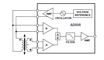
The IC needs just a few external passive components to set frequency and gain, and it converts the raw LVDT output to a scaled DC signal (Figure 2). It uses two synchronous-demodulation channels are used to detect primary and secondary amplitude. The AD698 divides the output of the secondary by the amplitude of the primary and multiplies by a scale factor. This eliminates scale-factor errors due to drift in the amplitude of the primary drive, thus improving temperature performance and stability. It uses a ratiometric architecture, so no adjustments are necessary while temperature stability is improved. Doing so also eases transducer interchangeability.

Q: What about Texas Instruments?
A: The PGA970 is an LVDT signal conditioner which includes A/D converters and other digital functions, in addition to the analog front end (Figure 3). The three-channel, low-noise, programmable-gain, analog front end, followed by three independent 24-bit delta-sigma A/D converters. The device also contains a digital signal demodulation block that interfaces to an integrated ARM-Cortex M0 MCU to implement custom sensor-compensation algorithms stored in its nonvolatile memory. External I/O is accomplished via SPI, OWI, GPIO, or PWM digital interfaces.
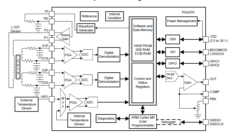
Besides the primary functional components, the PGA970 is equipped with device diagnostics, sensor diagnostics, and an integrated temperature sensor to provide protection and information about the integrity of the overall system and LVDT.
Conclusion
The LVDT is not only a distinguished and very widely used position sensor due to its combination of precision and multifaceted ruggedness but the electronics needed to drive the primary side and demodulate the secondary-side signal are a good fit for analog ICs. As a result, it continues to be a popular sensor in many scientific, industrial, and aerospace applications.
EE World References
LVDT position sensor, Part 1: Basics and principles
LVDT position sensor, Part 2: Characteristics
The proving ring – An alternative to dead-weight calibration, Part 2
Miniature LVDT Position Sensors Operate In Applications With Harsh, High-Pressure Environments
Miniature LVDT sensors provide accurate position/path measurements in tight spaces
Radiation Resistant LVDT Linear Position Sensor Designed For Nuclear Power Generation Plants
LVDT position sensors provide feedback in robotic applications
High-Pressure And Seawater-Resistant Position Sensors
Extreme High-Temperature Position Sensors
External References
S. Patent 2,196,809, “Telemetric System”
Sensor Wiki, “Linear Variable Differential Transformer (LVDT)”
Wikipedia, “Linear variable differential transformer”
TE Connectivity, “LVDT Tutorial”
Omega Engineering, “What is a LVDT?”
H.G. Schaevitz LLC/Alliance Sensors Group, “LVDT Position Sensor Products”
Analog Devices, “Linear Variable Differential Transformers”
Analog Devices, “Two New LVDT Interface ICs Offer Choice of Analog or Digital Output”
Analog Devices, ”Precision LVDT Signal Conditioning Using Direct RMS to DC Conversion”
Analog Devices, “Low Power LVDT Signal Conditioner with Synchronous Demodulation”
Analog Devices, “AD698 Universal LVDT Signal Conditioner”
Analog Devices, “CN0288 LVDT Signal Conditioning Circuit”
Texas Instruments, “Ratiometric measurements in the context of LVDT-sensor signal conditioning”
Texas Instruments, “PGA970 Use Case for LVDT Applications“
Texas Instruments, “PGA970 LVDT Sensor Signal Conditioner”


