The PIGA is the oldest accelerometer, is widely used in rocketry and guidance, and is still the best — but MEMS-based devices are getting closer.
When you see an inexpensive drone, a more sophisticated one, an unmanned aircraft, a standard piloted aircraft, guided or intercontinental ballistic missile ICBM), an underwater drone or submarine, or a spacecraft, they all have one requirement: the need for an inertial measurement unit (IMU). This unit provides critical guidance, navigation, and control (GNC) functions, so the vehicle will know where it is with respect to its starting point, its travel path, and even its target (assuming there is one). GNC overlaps with PNT—position, navigation, and timing—and provides similar functionality.
The IMU consists of two main functional blocks: a gyroscope assembly which provides information about the vehicle’s three-dimensional (3D) orientation and rotation in space relative to its initial setting, and a trio of orthogonal accelerometers which measure that parameter’s translation (displacement) along x, y, and z axes (sometimes referred to as pitch, roll, and yaw axes) (Figure 1). The vehicle’s position and track can be determined by combining the gyro’s orientation signals with the first integral of the acceleration signal (representing speed) and the second integral (distance).
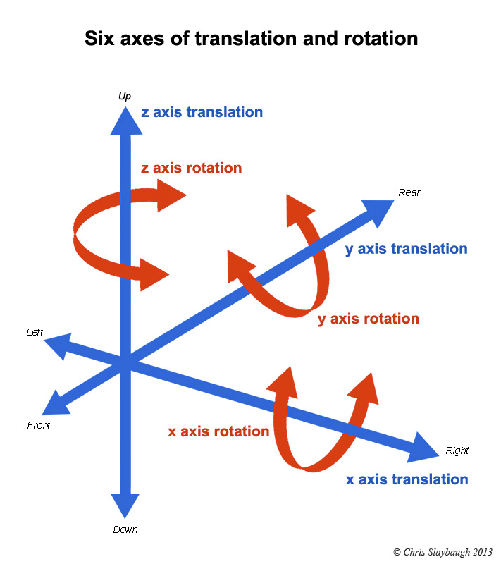
An inertial system requires no information or signals from the “outside”, such as sighting landmarks, stars, the surrounding environment, or radio emissions. It is a sealed device and so cannot be blocked or locked out, which is its outstanding attribute. Its underlying “sensing” is due to the response (inertia) of a mass when subject to acceleration; think F = ma. (Note that some vehicles, such as cars, may only need x-y position information, with no need for the z-axis.)
If available, why not use GNSS such as GPS for the GNC function? There are several reasons: first, there is no GNSS in space, obviously, nor does GNSS work underwater, in “dead” zones such as canyons or inside buildings. Further, GNSS systems are subject to jamming, interference, and even spoofing.
IMU technologies
Today’s IMUs are miracles of MEMS technology. They are small, lightweight, low power, low cost, and impressively accurate – at least up to a point. Even though the technology is radically different from predecessor IMUs which did not use MEMS, they do leverage many of the insights gained from their predecessors, the primarily mechanical gyroscope and accelerometer. Many of the equations and algorithms used to resolve the rough IMU data, extract useful information, and even correct it for various errors due to imperfections or subtle physics effects were developed with these mechanical units.
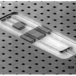
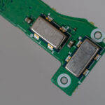
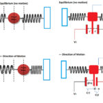
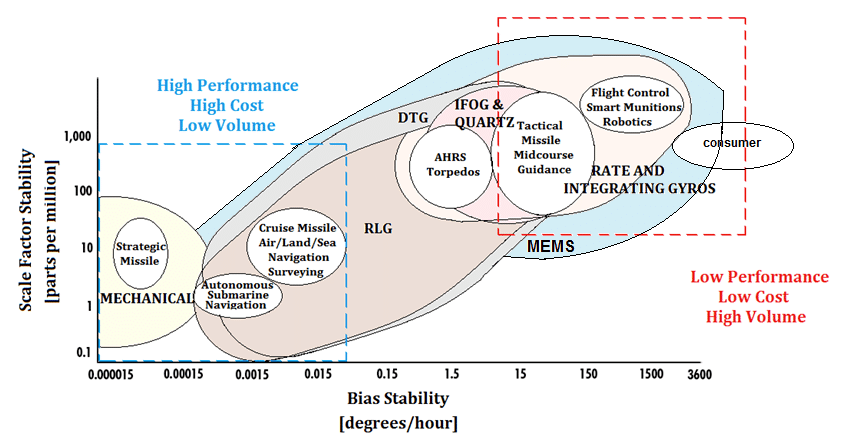
IMU technology can be based on these older mechanical technologies, ring laser gyros (RLG), dynamically tuned gyros (DTG), interferometric fiber-optic gyros (IFOG), and MEMS (Figure 2). Two of the many figures of merit for IMU gyros and systems are scale factor stability and bias stability, and there are differences of several orders of magnitude among these various technologies. At present, MEMS devices have the lowest performance, but it is rapidly improving, while the performance they offer is more than adequate for many applications, especially given their virtues with respect to size, weight, power, and cost.
The PIGA
Even with the development of MEMS-based IMUs, the most accurate accelerometer for an IMU is the pendulous integrating gyroscopic accelerometer or PIGA. This highly evolved, refined, and advanced accelerometer provides the highest attainable performance, far better than what is available via a MEMS-type unit. The PIGA has the highest linearity, accuracy, sensitivity, stability, and dynamic range of any accelerometer but at a severe acknowledged penalty in size, weight, power, complexity, cost, and maintenance.

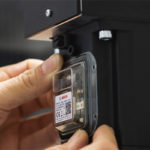
In a classical IMU, the three PIGAs are mounted on the gimbaled platform along with the three gyros (or a single three-axis gimbaled gyro) as a very complicated mechanical assembly (Figure 3 and Figure 4). Much of the work on transitioning the gyro, PIGA, and IMU from a somewhat useful device into the ultra-precise unit it became was led by the late innovator, scientist, engineer, manager, and unstoppable project-driver Dr. Charles Stark Draper at the MIT Instrumentation Lab; now an independent non-profit organization re-named as The Charles Stark Draper Laboratory, Inc.

The PIGA is conceptually simple, but achieving the superior performance has taken decades of relentless pursuit along multiple paths. First, there’s the need to fully understand sources of error from large to amazing subtle. Second, there is the actual implementation of improvements spanning design, fabrication, and test, based on ways to overcome, negate, or compensate for error sources.
The next part of this article looks at the PIGA operation and design details.
Related EE World content
Inertial Measurement Units: The hidden key to Apollo success, now a MEMS device (Part 1)
Inertial Measurement Units: The hidden key to Apollo success, now a MEMS device (Part 2)
Coriolis flowmeters: A subtle global effect with local applications, Part 1: The challenge
Coriolis flowmeters, Part 2: The principle
Coriolis flowmeters, Part 3: Flowmeter design
Coriolis flowmeter, Part 4: The future
What are inertial sensors?
Gyroscopes, Part 1: Context and mechanical designs
Gyroscopes, Part 2: Optical and MEMS implementations
GPS, Part 1: Basic principles
GPS, Part 2: Implementation
Additional References
- (book) Donald MacKenzie, MIT Press, “Inventing Accuracy: A Historical Sociology of Nuclear Missile Guidance” (don’t be fooled by the odd title: this excellent book is cited by almost every other article discussing the history of inertial guidance)
- (book) Thomas Wildenberg, Naval Institute Press, “Hot Spot of Invention: Charles Stark Draper MIT and the Development of Inertial Guidance and Navigation“
- AIAA, “Inertial Instruments: Where to Now?“
- Aerospace Research Central, “The pendulous integrating gyroscope accelerometer (PIGA) from the V-2 to trident D5, the strategic instrument of choice“
- AIAA/The Charles Stark Draper Laboratory, Inc., “Inertial Instruments: Where to Now?“
- Gordon A. Thompson (MIT MS Thesis), “Inertial Measurement Unit Calibration using Full
Information Maximum Likelihood Optimal Filtering“ - Wikipedia, “PIGA accelerometer“
- Kaiser and Allen, “A Micromachined Pendulous Oscillating Gyroscopic Accelerometer” or here
- AIAA/The Charles Stark Draper Laboratory, Inc., “The Silicon Oscillating Accelerometer:
A MEMS Inertial Instrument for Strategic Missile Guidance“ - Journal Aerospace Lab, “Gravitation and Geodesy with Inertial Sensors, from Ground to Space“
- Military-Aerospace Electronics, “Boeing to upgrade missile guidance systems on Minuteman III land-based nuclear rockets“
- Aerospace Research Central, “Inertial Components: Past, Present, and Future“
- Draper Technology Digest, “MEMS Development at Draper Laboratory“
- David Darling, “Inertial Guidance“
- V2 Rocket History, “Technology, People, and Places“
- The V2 Rocket, “A-4/V-2 Resource Site“
- TRW/Minuteman Missile, “Minuteman Weapon System: History and Description“
- Defense World, “Boeing Wins $17M PIGA Manufacturing for ICBM Subsystem Contract“

