The PIGA is the oldest accelerometer and widely used in rocketry and guidance, and still the best – but MEMS-based devices are getting closer.
At the core of each single-axis PIGA is a gyroscope. The performance of this gyro — which is unrelated to the orientation gyros — plays a large role in determining the performance of the PIGA. It also means that advances in gyro technology benefit both the orientation-function gyros and the PIGA gyros.
So how do you use a rotating gyroscope which tries, by its inherent nature, to maintain a fixed orientation in space to measure linear acceleration instead? The PIGA begins with basic gyroscopic theory, where its fast-spinning mass called the momentum wheel or rotor generates angular momentum about the spin axis. The rotor is supported by a housing called the torque-summing member (TSM) that allows rotation of the wheel about a second axis that is perpendicular to the spin axis (Figure 1).
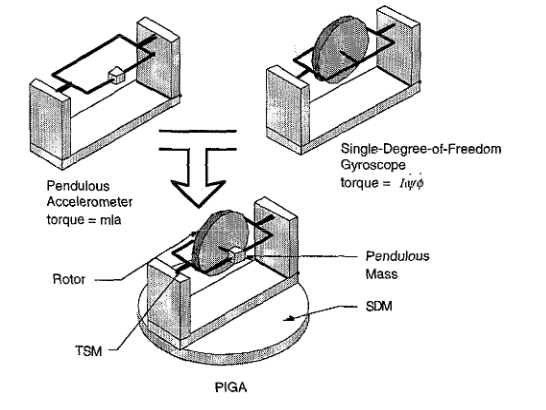
This combination of components is a single-degree-of-freedom gyroscope. It’s the rotation of the gyro about a third axis that is perpendicular to both the TSM and rotor axes that generates a gyroscopic torque on the TSM and which acts to rotate the TSM. The third axis is usually referred to as the input axis, and the TSM axis is usually referred to as the output axis.
A PIGA is created from the above gyroscope by making the TSM “pendulous” and mounting the gyro onto a member that allows the rotation of the gyro about its input axis. This member is referred to as the servo-driven member (SDM). The TSM is made pendulous by adding a mass m to the TSM, usually along the spin axis at some moment arm (designated as l), from the output axis.
The result is an arrangement that sums a pendulous and gyroscopic torque on the same member, the TSM. Since acceleration varies the pendulous torque, the gyroscopic torque can be servoed by rotating the SDM to balance the pendulum and hence hold the TSM at null. At this null, the rotation of the SDM can be related to the input acceleration. The SDM is equipped with a resolver or encoder to measure the SDM rotation angle, proportional to the input acceleration’s time integral – hence the “integrating” in the PIGA name.
Mathematically, the equilibrium-torque equation shows:
(mass m × moment arm l × acceleration) =
(moment of inertia of the rotor about the spin axis I × angular velocity of the rotor × angular velocity of the SDM)
(Note: any detailed discussion or analysis related to gyros and accelerometers and their performance and errors is inherently and intensely dependent on equations and advanced math. We’ll leave that aspect to the many available references.)
PIGA, intuitively
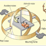
While this explanation is accurate and has the needed equations, it may not be intuitive even to someone with adequate background in physics. Another way to understand the PIGA’s operation is this: the sensing element of a PIGA is a pendulous mass that is free to pivot by being mounted on a bearing. A spinning gyroscope is attached such that it would restrain the pendulum against “falling” in the direction of acceleration. The pendulous mass and its attached gyroscope are mounted on a pedestal so that an electric torque motor can rotate. The rotational axis of this pedestal is mutually orthogonal to the gyroscope’s spin axis, as well as the axis that the pendulum is free to move in. The axis of rotation of this pedestal is also in the direction of the measured acceleration.
The pendulum’s position is sensed by precision electrical contacts or optical or electromagnetic means. The sensing mechanism operates the torque motor when acceleration displaces the pendulum arm from its null position. It rotates the pedestal such that the property of gyroscopic precession restores the pendulum to its null position. The rate of rotation of the pedestal gives the acceleration, while the total number of rotations of the shaft gives the speed. This is the source of the term “integrating” in the PIGA acronym. In most implementations of the PIGA, the gyroscope itself is cantilevered on the end of the pendulum arm to act as the pendulous mass itself.
The integration of shaft rotations is now done electronically but can be done by a mechanical scheme using a ball and disk integrator and used to record the displacement or distance traveled. This mechanical method was used in early guidance systems before electronics were available (even before digital computers, and was pioneered by the designers of the deadly German V-2 rocket in World War II (more this later).
From pretty good to outstanding
The difference between an adequate gyroscope at the heart of the PIGA (and the IMS) and a highly accurate one involves extremely sophisticated analysis of error sources as well as mechanical perfection and various types of compensation for sources of imperfection. For example, low static friction (stiction) in the bearings of the pendulum is critical for accuracy, and this has been achieved by various techniques. One technique uses a double ball bearing with a superimposed oscillatory motion to “dither” the bearing above its threshold or uses pressurized gas or fluid bearings rather than ball bearings.
Another example is the near elimination of the effect of gravity pulling on the mass of the gyro rotor. This puts a small but still significant force and thus noise on the unit shaft, rotor, and bearings. One approach “floated” the gyro in a high-density non-conductive silicone-based fluid to achieve a near-neutral buoyancy. This provided an improvement but was still left a tiny residual effect and was not adequate for the highest performance levels, such as needed by a ballistic missile going thousands of miles. As a further refinement, the temperature of this buoyancy fluid was controlled and stabilized. Hence, its viscosity was constant and so became a third- or fourth-order, admittedly minuscule error source. This shows the level of identification of error sources associated with the high-performance gyro and PIGA.
The final part of this article will look briefly at the history of the PIGA as well as the MEMS-based extension of the concept, which has replaced the gyro-based PIGA in many applications.
Related EE World content
Inertial Measurement Units: The hidden key to Apollo success, now a MEMS device (Part 1)
Inertial Measurement Units: The hidden key to Apollo success, now a MEMS device (Part 2)
Coriolis flowmeters: A subtle global effect with local applications, Part 1: The challenge
Coriolis flowmeters, Part 2: The principle
Coriolis flowmeters, Part 3: Flowmeter design
Coriolis flowmeter, Part 4: The future
What are inertial sensors?
Gyroscopes, Part 1: Context and mechanical designs
Gyroscopes, Part 2: Optical and MEMS implementations
GPS, Part 1: Basic principles
GPS, Part 2: Implementation
Products
MEMS inertial accelerometers target spacecraft electronics testing
Tactical grade, force-rebalance SMD MEMS accelerometer includes digital interface
Gyroscope/accelerometer combo enables high-precision motion sensing
MEMS inertial accelerometer now offered in ±10 g and ±50 g ranges
Additional References
- (book) Donald MacKenzie, MIT Press, “Inventing Accuracy: A Historical Sociology of Nuclear Missile Guidance” (don’t be fooled by the odd title: this excellent book is cited by almost every other article discussing the history of inertial guidance)
- (book) Thomas Wildenberg, Naval Institute Press, “Hot Spot of Invention: Charles Stark Draper MIT and the Development of Inertial Guidance and Navigation”
- AIAA, “Inertial Instruments: Where to Now?”
- Aerospace Research Central, “The pendulous integrating gyroscope accelerometer (PIGA) from the V-2 to trident D5, the strategic instrument of choice”
- AIAA/The Charles Stark Draper Laboratory, Inc., “Inertial Instruments: Where to Now?”
- Gordon A. Thompson (MIT MS Thesis), “Inertial Measurement Unit Calibration using Full
Information Maximum Likelihood Optimal Filtering” - Wikipedia, “PIGA accelerometer”
- Kaiser and Allen, “A Micromachined Pendulous Oscillating Gyroscopic Accelerometer” or here
- AIAA/The Charles Stark Draper Laboratory, Inc., “The Silicon Oscillating Accelerometer:
A MEMS Inertial Instrument for Strategic Missile Guidance” - Journal Aerospace Lab, “Gravitation and Geodesy with Inertial Sensors, from Ground to Space”
- Military-Aerospace Electronics, “Boeing to upgrade missile guidance systems on Minuteman III land-based nuclear rockets”
- Aerospace Research Central, “Inertial Components: Past, Present, and Future”
- Draper Technology Digest, “MEMS Development at Draper Laboratory”
- David Darling, “Inertial Guidance”
- V2 Rocket History, “Technology, People, and Places”
- The V2 Rocket, “A-4/V-2 Resource Site”
- TRW/Minuteman Missile, “Minuteman Weapon System: History and Description”
- Defense World, “Boeing Wins $17M PIGA Manufacturing for ICBM Subsystem Contract”