Inertial sensors are used to transduce inertial force into measurable electrical signals to measure acceleration, inclination, and vibration of an object. Micromachining technology has made it possible to produce MEMS (Micro Electromechanical System) inertial sensors using single-crystal silicon sensor elements. These micron-sized sensors meet all major system design drivers like low-cost, high performance, high precision, and small form-factor. Based on the same principles as of macroscopic inertial sensors, MEMS inertial sensors can detect the slightest change in position, orientation, and acceleration of an object several metres long using a sensor unit as small as few micro-meters in dimensions.
There are mainly two types of MEMS inertial sensors – accelerometers that measure linear acceleration in one or more axis, and gyroscopes that measure angular motion. These sensors are manufactured for use in specific applications as each application requires inertial sensors having different bandwidth, resolution, and dynamic range. For example, the inertial sensor used in the automotive airbag release system must have a bandwidth up to 0.5 KHz, resolution of around 500 mG and dynamic range of about +/-100G. While inertial sensor used in a space microgravity measurement instrument can have a bandwidth of 0-10 Hz, but must have a resolution as precise as < 1 µG and dynamic range less than +/- 1G.
The inertial sensors are generally part of a larger control system in any application or device. Mere information of acceleration or angular movement of an object is of no use. The information collected from inertial sensor is always used to control movement of the device itself or is used for activating an actuator, like to open an airbag of a car.
Applications of inertial sensors
There was a time when building inertial sensors was a costly affair and their use was restricted to military and aerospace applications. The development of MEMS inertial sensors has opened the possibilities and use of inertial sensors in automotive and various consumer electronics segments.
In the automotive industry, accelerometer is used for airbag release control, traction control, seat belt control, active suspension, antilock braking system (ABS) and monitoring vehicle vibrations. While the gyroscope is used for rollover protection, automatic indicators, power steering and to control vehicle dynamics.
In consumer segment, inertial sensors are used in a variety of applications like platform stabilization in video cameras, virtual reality headsets, pointing devices for computers, intelligent toys and gaming keypads. All smartphones and tablets nowadays have inertial sensors for detecting screen rotation, gaming and augmented reality applications.
The inertial sensors are also used to monitor position and orientation of robotic manipulators and unmanned robotic vehicles. In medical applications, these sensors are used for monitoring patients with specific conditions like for monitoring patients having Parkinson’s disease. High-end inertial sensors are used in military and aerospace applications like smart ammunition, aircraft dynamics control, crash detection, seat ejection system in aircrafts, and microgravity measurement.
Accelerometers
Accelerometers consist of a mechanical sensing element that can measure acceleration in one or more axis. The sensing element consists of a proof mass attached to a reference frame by a mechanical suspension system. In MEMS sensors, proof mass is an extremely small seismic mass and the suspension system is built from silicon springs.
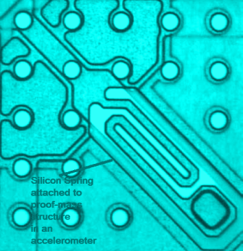
The proof mass deflects from its stable position whenever the sensor experiences some inertial force due to acceleration. Newton’s second law of motion governs this. The deflection of the proof mass to acceleration is expressed by a Laplace equation as follows:
x/a = 1/(s2 + b/m + s*k/m)
Where,
x is displacement of proof mass,
a is acceleration,
s is Laplace operator,
b is damping coefficient,
m is mass of the proof mass,
k is the mechanical spring constant of the suspension system.
The following equation gives the resonant frequency of the sensor:
fn = √(k/m)
The following equation gives the quality factor:
Q = √(m*k)/b
The following equation gives the sensitivity of the sensor (in open loop):
S = m/k
You can see, then, that if the sensitivity is increased, resonant frequency decreases and vice-versa. This trade-off can be adjusted with a closed-loop system. The damping coefficient determines the maximum bandwidth of the accelerometer. In MEMS accelerometers, damping coefficient is often variable and increases with displacement of the proof mass.
In all types of micro-machined accelerometers, the displacement of the proof mass is measured by position measuring interfaces, like in a capacitive measurement, there are movable plates attached to proof mass which move along the proof mass between fixed capacitive electrodes. There are many types of sensing mechanisms that are used in the design of accelerometers. Some of the common sensing methods include piezoresistive, capacitive, piezoelectric, optical, and tunnelling current.
The accelerometer can have open-loop or closed-loop system. If the electrical signals from the position measurement interface are directly used as the output signals, it is called open-loop accelerometer. Most of the accelerometer sensors are open-loop as they are easy to build. However, open-loop accelerometers have to manage with high tolerances due to variable spring constant, variable damping coefficient, and non-linear proof mass displacements.
In a closed-loop accelerometer, there is a feedback system that applies a feedback force to the proof mass proportional to its acceleration putting the proof mass back to its rest position. This way, the non-linear factors are cancelled out, sensitivity gets dependent on the feedback control and dynamics of the sensor can be precisely controlled using an electrical signal controller. The proof mass can be placed back to its rest position using electrostatic, thermal or magnetic actuation. The feedback signal controlling the feedback force can be analog or digital. All this adds more complexity to the sensor design.
Acceleration sensing methods
There are many ways in which accelerometers sense acceleration in a particular axis. Some of the acceleration sensing methods are described below:
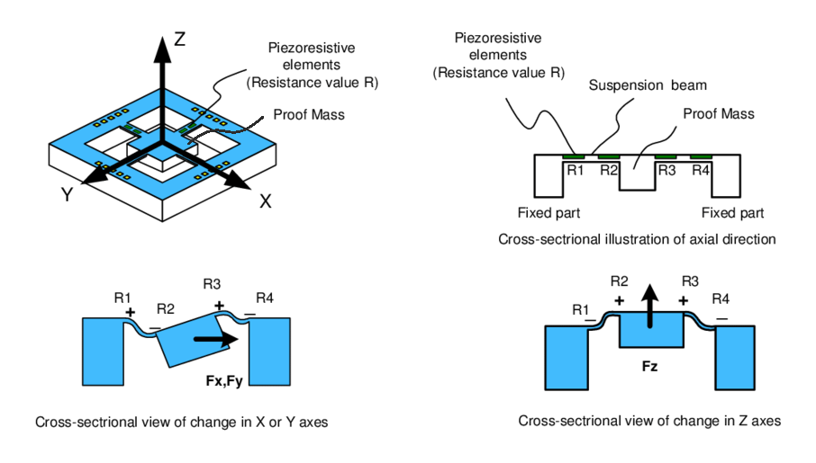
- Piezoresistive Accelerometers – In these type of accelerometers, the proof mass is attached to a piezoresistor. The resistor is connected to read-out electronic circuit. When there is displacement in proof mass, there is a change in the resistance of the piezoresistor proportional to the applied force. These types of accelerometers are the first one to see bulk production. The biggest drawback of these type of accelerometers is their thermal stability. The peizoresistance can significantly change due to thermal noise and can lead to false outputs.
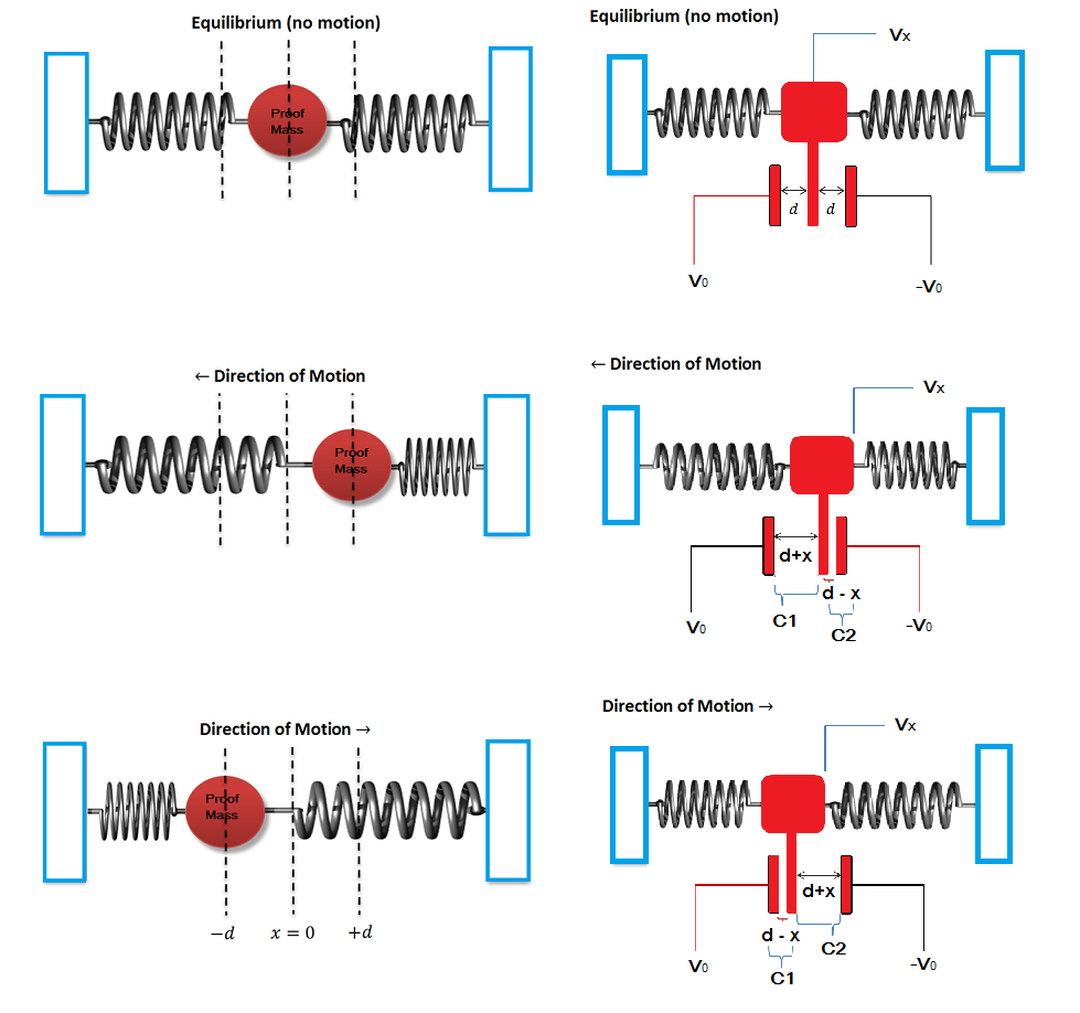
Example showing working principle of piezoresistive accelerometers - Capacitive Accelerometers – In capacitive accelerometers, capacitive sense fingers are attached to the proof mass which move along a given axis with the displacement of the proof mass. Each movable plate is placed between two electrodes. When there is an acceleration, the proof mass displaces in the direction opposite to the direction of motion and the variable plate moves along the proof mass. The change in the position of variable plate along an axis cause change in its distance with fixed electrode plates and cause symmetrical change in capacitance. This is then measured as electrical output by a read-out electronics. The capacitive accelerometers are thermally stable, but are prone to electromagnetic interference, where they can give false outputs due to parasitic capacitance.
Example showing working principle of capacitive accelerometers - Piezoelectric Accelerometers – Most of the macroscopic accelerometers use piezoelectric materials for detecting motion of proof mass. Many micro-machined accelerometers also use the same principle. These accelerometers have great bandwidth, but have extremely poor resonant frequency due to leakage currents. The piezoelectric material produces electrical signals proportional to the displacement of the proof mass in a given axis.

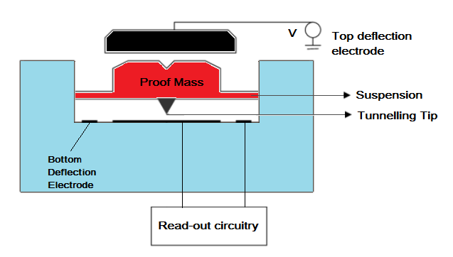
Example showing working principle of piezoelectric accelerometers - Tunnelling Accelerometers – These types of accelerometers use tunnelling current for measuring the displacement of the proof mass. The tunnelling current between a sharp tip and an electrode changes exponentially by the tip-electrode distance. The following equation gives the tunnelling current:
I = I0 * exp(-ᵦ√(φz))
Where,
I is Tunnelling current between tip and electrode,
I0 is scaling current depending upon the material used,
ᵦ is conversion factor,
φ is tunnel barrier height in eV,
and z is tip-electrode distance.
- Resonant Accelerometers – In a resonant accelerometer, the proof mass is attached to a resonator. The displacement of the proof mass changes the strain of the resonator and so its resonant frequency. The change is frequency is converted to digital electrical signals using a frequency counter circuit. These accelerometers are quite immune to noise and are highly reliable as frequency changes can be directly converted to digital format.
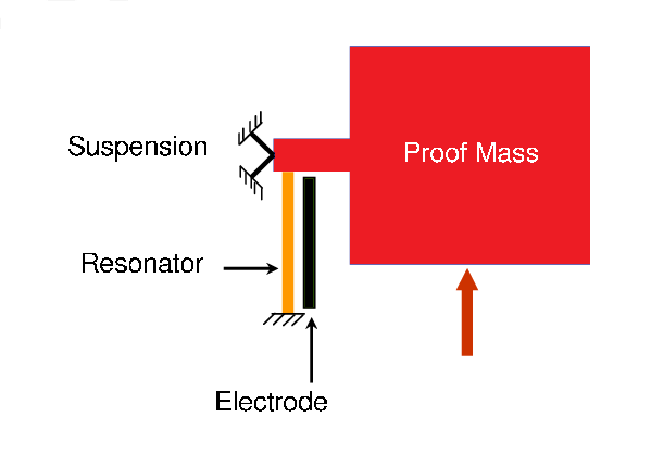
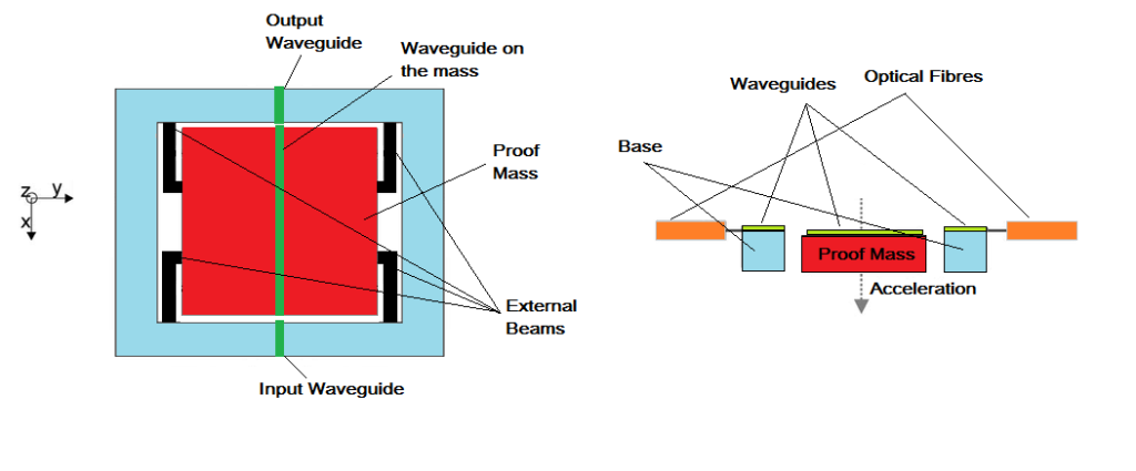
Example showing working principle of resonant accelerometers - Optical Accelerometers – These accelerometers use optical fibres and wave guides attached to the proof mass. However, optical fibre type accelerometers are not suitable for batch fabrication as the fibre needs to be manually installed near the proof mass in the sensor assembly. Another type of optical accelerometers use LED and PIN photo detectors to measure displacement of the proof mass. The optical accelerometers have the advantage that they are free from electrostatic and electromagnetic interference. But, because they usually involve a complex assembly and read-out circuitry, they are not much popular.
Gyroscopes
A gyroscope measures the rotation of an object. The MEMS gyroscopes use the principle of Coriolis force. When a mass moves in a rotating system, it experiences a force perpendicular to axis of rotation and the direction of motion. This is called Coriolis force. A MEMS gyroscope consists of a mechanical structure that is driven into resonance due to Coriolis force and excites secondary oscillation in the same or a secondary structure. The secondary oscillation is proportional to the rotation of the structure in a given axis. The Coriolis force has relatively small amplitude compared to its driving force. That is why, all MEMS gyros use a vibrating structure that use the phenomenon of Coriolis force.
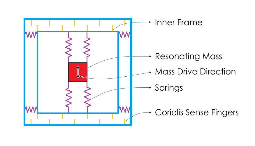
The vibrating structure consists of proof mass that is connected to a inner frame by a pair of springs. The inner frame is connected to an outer frame by another set of orthogonal springs. There are capacitive sense fingers between the inner frame and the outer frame attached along the orthogonal springs. The Coriolis force is proportional to both the angular velocity of the rotating object as well as velocity of the object towards or away the axis of the rotation. The proof mass is continuously driven sinusoidally along the inner springs. When the system experiences rotation, the resonating proof mass experiences Coriolis force along the orthogonal springs attached between inner and outer frame. This changes the distance between the capacitive sense fingers and so an electrical signal proportional to Coriolis force is output. As the Coriolis force is proportional to angular velocity, the electrical signal due to it is also proportional to the angular velocity of the system.

