There’s a wide range of vibration sensor technologies, and each technology has unique performance characteristics that make it suited for a specific type of applications ranging from mobile devices to machine condition monitoring and automotive safety testing.
This FAQ reviews vibration and accelerometer sensor technologies including charge mode versus voltage mode piezoelectric sensors, MEMS devices, and piezoresistive vibration sensors. It looks at integrated electronics in various types of accelerometers and closes with a look at how artificial intelligence (AI) is being integrated with accelerometers and machine condition monitoring systems.
Accelerometers are the most common type of vibration sensor. They are electromechanical devices that measure changing gravitational force (g) and convert it to a voltage or current signal. One g of gravitational force is defined as 9.8 meters per second squared (9.8 m/s2). Some types of accelerometers can measure down to 0 g. There are several ways to classify accelerometers. One basic classification consists of ac response versus dc response devices.
AC response accelerometers have AC-coupled outputs. They can’t measure static, 0 g, acceleration, or constant rates of acceleration. They are good at measuring dynamic events like high-speed vibrations, have wide frequency responses, and can have high signal-to-noise ratios.
A DC response accelerometer has a DC-coupled output and can measure static acceleration down to zero Hz (0 g). They are useful for measuring shock events as well as dynamic events. DC response accelerometers typically have narrower operating temperature ranges compared to AC response devices.
Another way to classify accelerometers is by their physical construction such as piezoelectric accelerometers that use a piezoelectric natural quartz crystal or lead zirconate titanate (PZT). When a force-like acceleration is applied, the crystal produces a proportional voltage. Most piezoelectric sensors are based on PZT ceramics which have a wide operating temperature range, broad dynamic range, and wide bandwidth (to > 10kHz). Two types of piezoelectric accelerometers are charge output and voltage output designs.
Charge mode piezoelectric
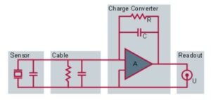
When housed in a high-performance case like a hermetic, welded stainless steel housing, a charge mode accelerometer can withstand extreme environmental conditions including very high temperatures and humidity. However, these devices have high impedance characteristics and must be connected using special low-noise cabling. When using standard coaxial cables, the output signal can become corrupted by the interference caused by the triboelectric effect and other noise sources. In addition, these accelerometers are generally used with an external charge converter (amplifier) at the opposite end of the cable (Figure 1). The dynamic range of the combined accelerometer and charge amplifier system can exceed 120 dB. These PZT sensors can operate down to -200 °C and up to 600+ °C, depending on the thermal management.
Voltage mode piezoelectric
Moving the charge amplifier inside the piezoelectric accelerometer produces a voltage mode device. Voltage mode piezoelectric accelerometers are available in 3-wire and 2-wire designs. Two-wire designs where the power and signal share a wire are the most common and are called integral electronics piezo-electric (IEPE) or integrated circuit piezoelectric (ICP) devices. IEPE/ICP construction is popular since it can use standard coaxial cabling (no special low-noise cable needed) with ac signal superimposed on the dc power line. The integrated electronics convert the high-impedance charge signal from the piezoelectric transducer into a low-impedance voltage signal that can directly connect to a data acquisition system or readout meter. A blocking capacitor is included to remove the dc bias from the sensor signal output (Figure 2).
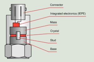
If the IEPE/ICP powering option is not available, a 3-wire (power, signal, ground) can be implemented. Both 2-wire and 3-wire IEPE/ICP designs have integrated electronics that are not included in charge mode accelerometers. While the integrated electronics simplify the cabling needs, it also reduces the thermal ruggedness. Standard designs are rated for operation up to 125 °C with some high-performance devices can operate up to 175 °C, in either case, much lower than the 600 °C rating of some charge mode devices.
The range of charge mode piezoelectric accelerometers can be adjusted as needed in the field using the remote charge amplifier. Voltage mode devices have their full-scale range fixed due to the internal amplifier that is not adjustable once the device has been assembled. In addition to the choice of current mode versus voltage mode piezoelectric accelerometers, designers can choose between two types of dc accelerometers, capacitive and piezoresistive.
Capacitive MEMS accelerometers
The most common type of accelerometers in use today are capacitive accelerometers based on micro-electro-mechanical systems (MEMS) technology. They can be manufactured in high volumes, at low cost, and can be very compact. They are found in a wide range of applications from mobile devices to airbags. They are also suited for use in civil engineering and similar applications for measuring low-frequency motion with low g levels.
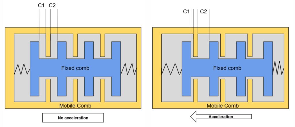
A MEMS accelerometer consists of a mobile comb and a fixed comb. Where there is no acceleration, the mobile and fixed combs are aligned such that all the capacitors have the same value. In the presence of acceleration in the proper axis, the mobile comb moves to create different capacitance values on each side of the comb (C1 and C2). The change in the capacitance values is proportional to the acceleration (v). Gas inside a MEMS accelerometer provides dampening of the vibrations and improved measurement results. Integrated analog-to-digital conversion and support electronics are used to produce the output signal based on variations in capacitance.
These accelerometers are limited in the precision they can deliver since they suffer from poor signal-to-noise ratio (SNR) and limited dynamic range. The signal conversion circuitry requires an internal clock. The clock signal can induce high-frequency noise in the output signal. These accelerometers are available in three-wire designs for standard outputs or four-wire implementations for differential outputs. These devices have good linearity and stability but have bandwidths limited to a few hundred Hz, with high-performance designs specified for up to 1.5 kHz, and acceleration under 200 g.
Piezoresistive accelerometers
Piezoresistive accelerometers use the piezoelectric element like a strain gage to produce changes in resistance. When the piezoelectric material is deformed, its resistance changes. This technology can produce accelerometers with bandwidths over 7 kHz, and they can be designed to operate with high g forces up to tens of thousands of g’s.
Many piezoresistive accelerometers are gas or fluid dampened. MEMS-based devices tend to be gas dampened while bonded strain gauge devices are often fluid-dampened. Damping is an important factor in some applications, it can prevent resonance or ringing and improve dynamic range. Most piezoresistive accelerometers are sensitive to changes in temperature. Temperature compensation can be internal to the sensor or applied externally. Most designs include an ASIC that performs signal conditioning as well as temperature compensation. The quality of the internal signal conditioning is key to supporting a wide dynamic range.
The broad bandwidth and mechanical ruggedness of these accelerometers make them suitable for measuring impulse, impact, and shock where the frequency range and g levels can be high. The DC output is easily read and not subject to integration and other errors that can result from the use of accelerometers that require a charge converter/amplifier like piezoelectric devices. These performance capabilities make piezoresistive accelerometers well suited for use in automotive safety testing and military systems testing where high ranges of shock are experienced than can be handled with MEMS-based devices.
AI and accelerometers
Like many other areas in electronics, AI is being used to improve accelerometer performance. Those improvements include better accelerometer operation and higher system-level performance for applications like pattern recognition and machine condition monitoring.
In one case, a MEMS-based accelerometer has an integrated machine learning core (MLC), finite state machine (FSM) anti-aliasing filtering for higher accuracy at lower sample rates, and other features for detecting motions. The integrated MLC supports AI algorithms that can make reliable activity detection and the FSM further enhances movement recognition. Integration of these functions into the accelerometer offloads a significant computing workload from the host system, supports faster system response, and lowers overall power consumption.
The integrated adaptive self-calibration (ASC) capability enables the accelerometer to autonomously adjust its settings for measurement range and frequency for performance optimization. The device includes an internal pedometer function to identify running, walking, and sitting, and the MLC enables designers to develop additional activity classes for automatic recognition in real-time.
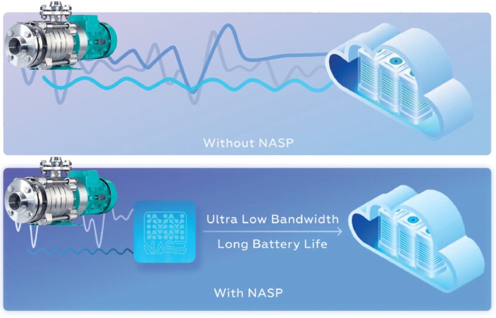
Another example of AI in accelerometers is the development of Neuromorphic Analog Signal Processing (NASP) technology to provide a solution to power consumption and computing latency tradeoffs by dramatically reducing data transfer requirements for applications like machine condition monitoring. An AI application has been developed to run on the NASP chip and locally analyze the data from accelerometers and other sensors used in machine monitoring, thereby reducing the amount of data that needs to be transmitted (Figure 4).
Summary
A variety of technologies have been developed for vibration sensing. They are widely used in accelerometers and offer various tradeoffs between sensitivity, range, linearity, stability, operating temperature ranges, and other characteristics that make them suitable for specific classes of applications. Most recently, AI is being applied to vibration sensing and accelerometers to improve the performance of the sensors themselves and the overall system.
References
5 rules for installation and mounting of piezoelectric force transducers, HBM
Accelerometers, SBG Systems
Accelerometers: Piezoelectric, MEMs, and Piezoresistive Accelerometers, Seeed Studio
AI chip solution for vibration monitoring sensor nodes, Polyn Technology
Choosing the Right Type of Accelerometer, TE Connectivity
Piezoelectric Transducers, Power MI
Ultralow-power accelerometer with AI & anti-aliasing, STMicroelectronics
Very low-frequency IEPE accelerometer calibration and application to a wind energy structure, European Academy of Wind Energy


