The Mars Environmental Dynamics Analyzer (MEDA) on the Perseverance rover is characterizing the surface weather as well as the dust particle size and morphology. Understanding dust behavior is a key to predicting Martian weather. Dust influences Mars’ weather the way that water controls Earth’s weather. Two of MEDA’s weather-related goals are: determination of the destructive potential of UV radiation, dust UV optical properties, photolysis rates, and oxidant production, and; estimating subsurface habitability based on ground-atmosphere interaction and temperatures.
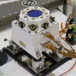
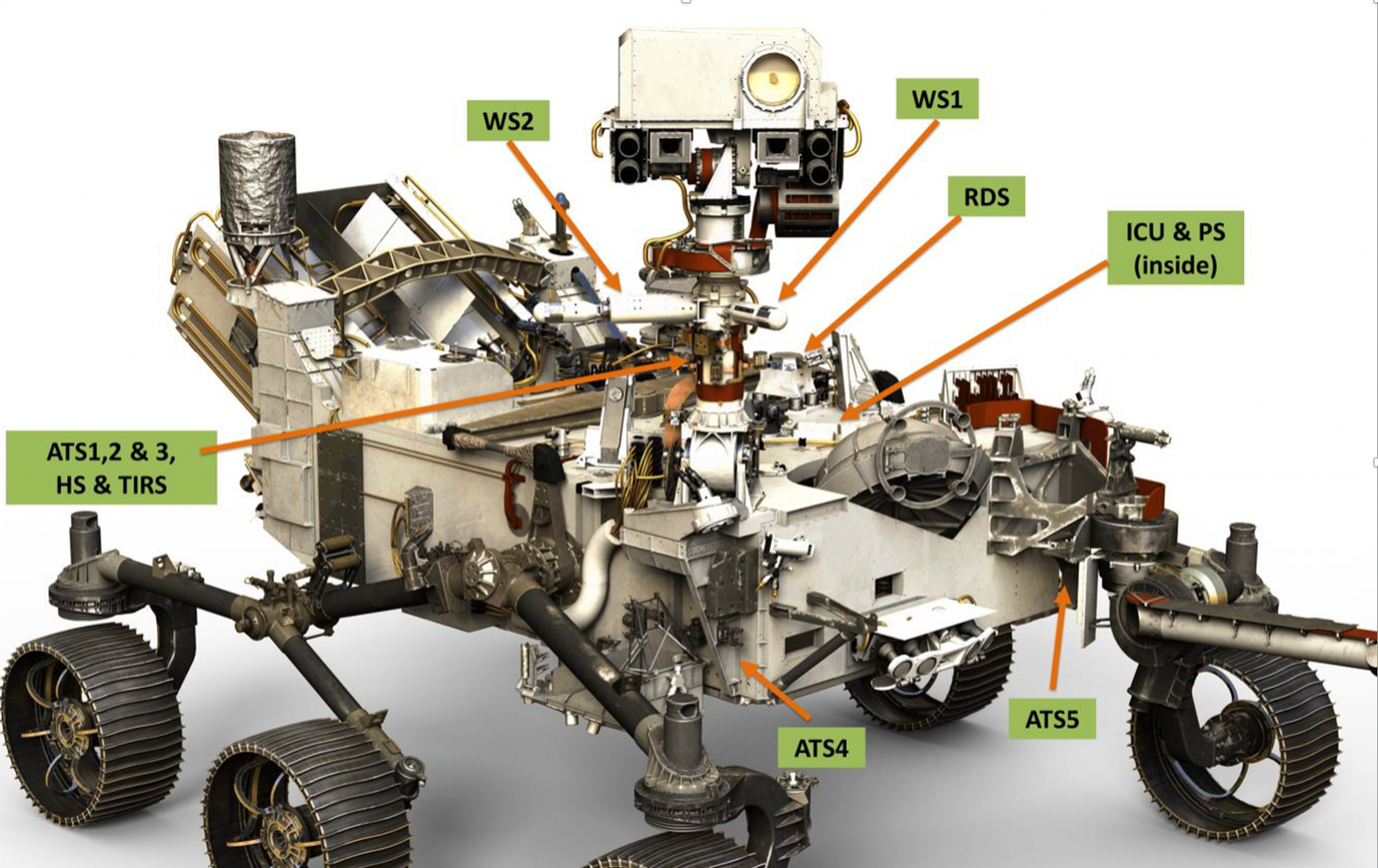
MEDA is a follow-on project from the Rover Environmental Monitoring Station (REMS) on the Curiosity rover. MEDA has an increased scope, with greater focus on data collection related to dust and radiation. In addition to the radiation and dust sensors, MEDA environmental sensors measure six atmospheric parameters: wind speed/direction, air and ground temperatures, pressure, relative humidity, and solar radiation (UV, visible, and IR). The MEDA instrument consists of a suite of sensors and a control unit (Figure 1):
- Wind Sensor, WS (two detectors, WS1 and WS2, placed on two booms)
- Wind Sensor 1 is 2 x 6.7 in (5 by 17 cm)
- Wind Sensor 2 is 2 x 15.75 in (5 by 40 cm)
- Air Temperature Sensor, ATS (five detectors: three of them placed on the RSM, and two more at the front of the rover body)
- Each sensor is 2.25 x 1 x 2.7 in (5.75 x 2.75 x 6.75 cm)
- Thermal Infrared Sensor, TIRS
- 5 x 2.25 x 2.25 in (6.25 x 5.75 x 5.75 cm)
- Relative Humidity Sensor, HS
- 2 x 1.0 x 2.8 in (5.5 x 2.5 x 7.25 cm)
- Radiation and Dust Sensor, RDS (it also includes the SkyCam imager)
- 2 x 4.5 x 5 in (13.2 x 11.5 x 12.5 cm)
- Pressure Sensor, PS (inside the Instrument Control Unit, ICU)
- ICU and pressure sensor, 5.5 x 5.5 x 5.1 in (14 x 14 x 13 cm)
Radiation and dust sensors
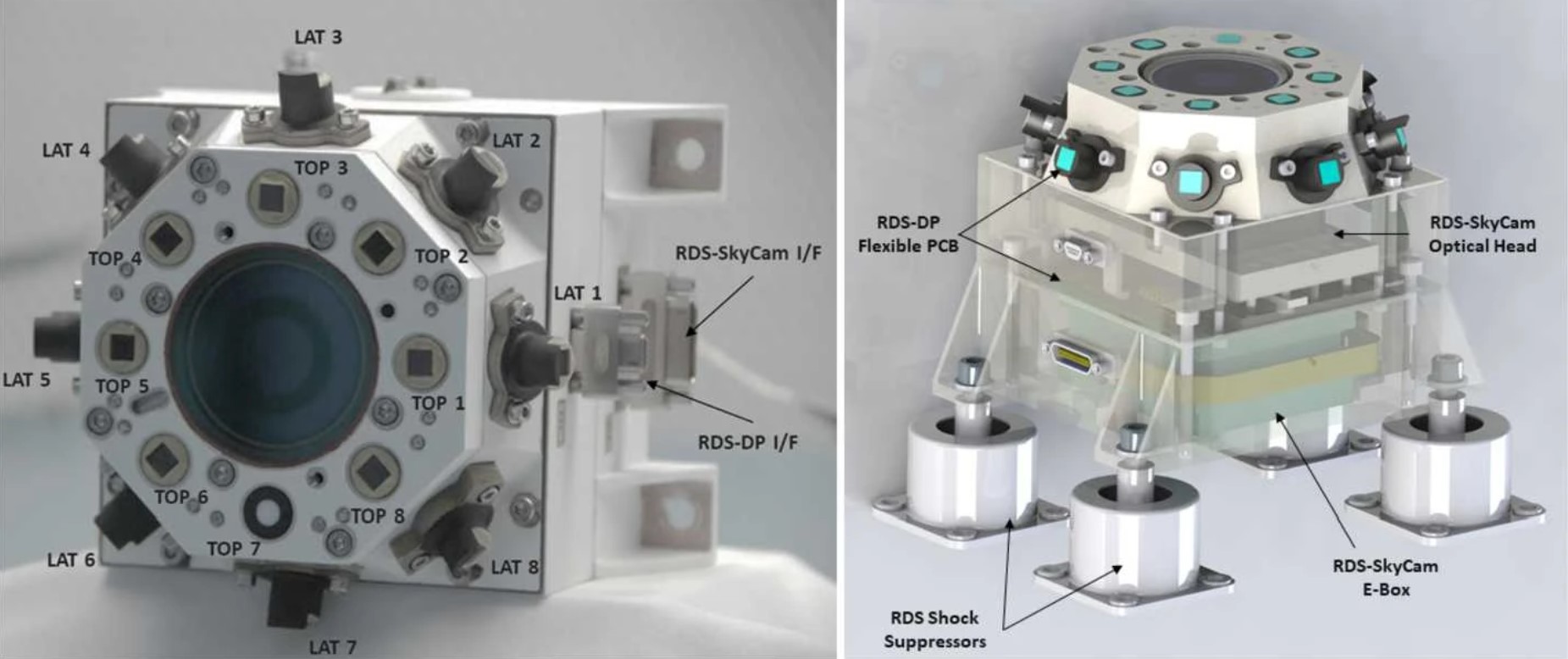
The MEDA radiation and dust sensor (RDS) uses a combination of direct sky imaging and sky-pointing multi-wavelength and azimuthal measurements of diffuse light to monitor the seasonal and diurnal changes in the aerosol optical depth, the aerosol phase function, and the amount of ozone. Diffuse light is measured over different wavelengths and angular directions using two sets of eight photodiodes part of the RDS-Discrete Photodetectors or RDS-DP. Sky imaging is accomplished using an upward-viewing wide-angle camera, the RDS-SkyCam. The RDS records data for five minutes every 30 minutes.
The RDS is the most electronically and mechanically complex sensor in the MEDA suite (Figure 2). It includes two sets of eight photodiodes used in the RDS-DP to measure the sky’s brightness as a function of both the wavelength and the azimuthal angle. The first set of photodiodes (TOP channels) points towards the zenith and covers a range of UV, visible and near-infrared wavelengths designed to distinguish between dust and water ice clouds and measure the aerosol particle size. The second group of eight photodetectors, the LAT channels, are pointed 20° above the horizon and distributed 45° in azimuth each. All lateral detectors have been designed to simultaneously measure the sky’s brightness at different directions with the objective to extract information of the dust shape and size.
The goals of the RDS-DP are:
- To estimate the particle size and refractive index of Martian dust by collecting the optical depth, single scattering albedo and phase function of dust particles as a function of season and local time.
- To determine the optical depth and altitude of water ice clouds and combine that data with the information collected on dust particles to support the study of dust particles as cloud condensation nuclei.
- To estimate the abundance of ozone as a function of season and local time, and to measure the influence of clouds on the ozone levels.
- To measure the solar radiation from UV to near-IR, and its daily and seasonal variations, on the surface of Mars.
Air temperature sensors
The air temperature sensors (ATS) use thermocouples to measure the air temperature vertical profile, and how it changes as the atmosphere transitions from an unstable daytime convection condition to a nighttime stable profile. The ATS includes three sensors distributed around the rover to correct for rover influences, as well as two sensors on the sides of the rover body to get a measurement of the vertical temperature gradient near the surface. The ATS provides temperature measurements at four heights: 0 m (at the surface), 0.84 m, 1.45 m and 40 m.
Pressure sensors
The pressure sensor (PS) is a micro-machined capacitive pressure sensor head. Pressure moves the capacitor plates in the sensor, changing its capacitance. The capacitance of the sensor is also temperature-dependent, so an accurate reference temperature measurement is needed to correctly interpret the output capacitance. MEDA PS contains two pressure transducers (oscillators) on the same multilayer PCB, each with its own controlling ASIC and eight channels containing capacitive sensors, temperature sensors, and constant reference capacitors. The temperature sensors are located directly on the PCB close to the pressure sensors to provide accurate housekeeping temperature measurements. The output of each of the eight channels in a transducer is a frequency, and the reference channels with constant capacitors are used for calculating the capacitances of the sensors from the frequency output.
Humidity sensors
The humidity sensors (HS) contain an active polymer that changes the sensor capacitance as a function of relative humidity and temperature with 0 to 100% relative humidity (RH) measurement range. At a given temperature, the response between 0 and 100% RH is nearly linear. The polymer reacts to the relative humidity even when the device is not powered, so RH can be read almost immediately after start up. The humidity sensor electronics are based on the same transducer architecture as the pressure sensors and include HS sensors, reference capacitors and PT1000 temperature sensors. All the sensors and related electronics are packaged on a single multilayer PCB protected by a round metallic perforated Faraday cage covered with a hydrophobic polytetrafluoroethylene (PTFE) dust filter. The HS are designed to improve the understanding of the water vapor flux between the surface and lower atmosphere. That will enable the development of better circulation models and improved water abundance estimates from satellites orbiting the planet.
Thermal infrared sensors
The thermal infrared sensors (TIRSs) use an infrared (IR) radiometer and five wavelengths to measure the downward and upward long wave (LW) thermal IR radiation at the surface, reflected short wave (SW) solar radiation at the surface, surface brightness temperature, and air temperature at about 40 m above the surface. The TIRSs are composed of the sensor and the electronic conditioning board. The sensor includes a housing, a support plate containing the five thermopiles, and the calibration plate. The support plate minimizes any thermal gradients in the thermopiles’ package and was used for in-flight calibrations before landing on Mars. Temperature references are provided by two redundant PT1000 temperature sensors.
Wind sensors
The MEDA wind sensors (WS) are contained in two booms placed at about 1.5 m above the base of the rover wheels and rotated 120° from each other around the rover mast (Figure 3). The Curiosity rover carried a predecessor of the MEDA wind sensor booms. The WS on Curiosity were damaged at the start of the mission, probably by rocks that hit it during landing. As a result, winds from the rear of the rover could not be accurately measured. In addition, noise in the boom’s electronics meant that winds could not be measured below a certain temperature, causing the loss of up to 12 hours of wind measurements overnight. Those problems were corrected with MEDA.
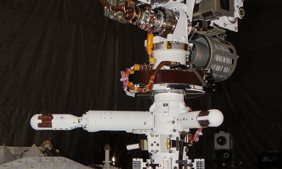
The placement of the two WS and their 120° separation were intended to mitigate rover hardware wind interference as much as possible. However, the mast itself affects wind flow patterns, so data collected simultaneously from both booms must be combined to produce valid wind speed and directional measurements. Each MEDA WS boom assembly has 6 wind sensor transducer boards, double the number used on Curiosity. The additional boards enable MEDA to more accurately measure vertical winds.
Summary
MEDA on Perseverance has an expanded set of goals compared with earlier missions such as Curiosity. Deeper understanding of the atmospheric dust and the destructive potential of UV radiation plus the ground-atmosphere temperature interaction will be important when planning future manned missions to Mars. MEDA environmental sensors are placed at various locations around and outside of the rover and measure six atmospheric parameters: wind speed/direction, air and ground temperatures, pressure, relative humidity, and solar radiation (UV, visible, and IR), in addition to UV radiation and dust.
References
Mars Environmental Dynamics Analyzer, Wikipedia
MEDA – NASA
MEDA – Mars Environmental Dynamics Analyzer, NASA
REMS for Scientists, NASA
The Mars Environmental Dynamics Analyzer, MEDA. A Suite of Environmental Sensors for the Mars 2020 Mission, Space Science Reviews