NASA is developing several sensor systems and algorithms for use on Artemis moon landings. It’s called the Safe and Precise Landing – Integrated Capabilities Evolution (SPLICE) technology suite. It consists of three primary elements: An inertial measurement unit (IMU) and a camera for terrain relative navigation. Second is Doppler LiDAR to determine the lander’s velocity and altitude. Third is a hazard detection LiDAR to scan the surface to create a 3D map of the landing field. It’s the spacecraft equivalent to an autonomous automobile.
Apollo astronauts were trained to identify specific lunar surface locations and features needed to navigate during a landing. They would look out the window and use those landmarks to gauge where they were relative to the intended landing zone and manually fly the lander to the intended location. The SPLICE terrain relative navigation (TRN) system will automate the same task on Artemis by comparing real-time images against preloaded lunar surface maps.
Landing in an ellipse
When a landing location is selected, part of the analysis is to ensure enough room for a safe landing. Due to the inexactness of landing technology, the landing zone is an ellipse, not a circle. The ellipse considers the rapid forward velocity of the lander compared with the much more limited potential for lateral movement. When the Apollo 11 astronauts performed a manual landing in 1968, the landing ellipse measured 11 x 3 miles. Early automated landing technologies needed even larger landing ellipses. When the Viking lander arrived at Mars in 1976, the landing ellipse required by the automated landing system was 174 x 62 miles. By 2012, the landing ellipse for the Curiosity Mars rover was reduced to 12 x 4 miles, almost as small as the Apollo landing zone. Using SPLICE technology on Artemis will enable multiple missions to safely land in an area smaller than the 11 x 3 miles ellipse used by the Apollo astronauts. SPLICE consists of four core technologies and capabilities:
- Navigation Doppler LiDAR
- Terrain Relative Navigation
- Hazard Detection LiDAR
- Descent and Landing Computer
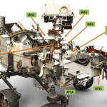
The various technologies are used at different points during the descent (Figure 1). Before the descent even begins, one or more satellites orbiting the moon will take a series of images and create maps of the approach and the landing ellipse. As Artemis descends, SPLICE’s TRN system will use a camera to capture up to ten surface images every second and compare them with the preloaded maps from the orbing satellite(s). Comparing the images in real-time, and fusing that information with data from the IMU sensor, enables the descent and landing computer (DLC) to calculate the lander’s position and avoid known hazards such as craters and hills. The SPLICE system will allow landings closer to areas of scientific interest, minimizing the need to use a rover to drive to the desired location.
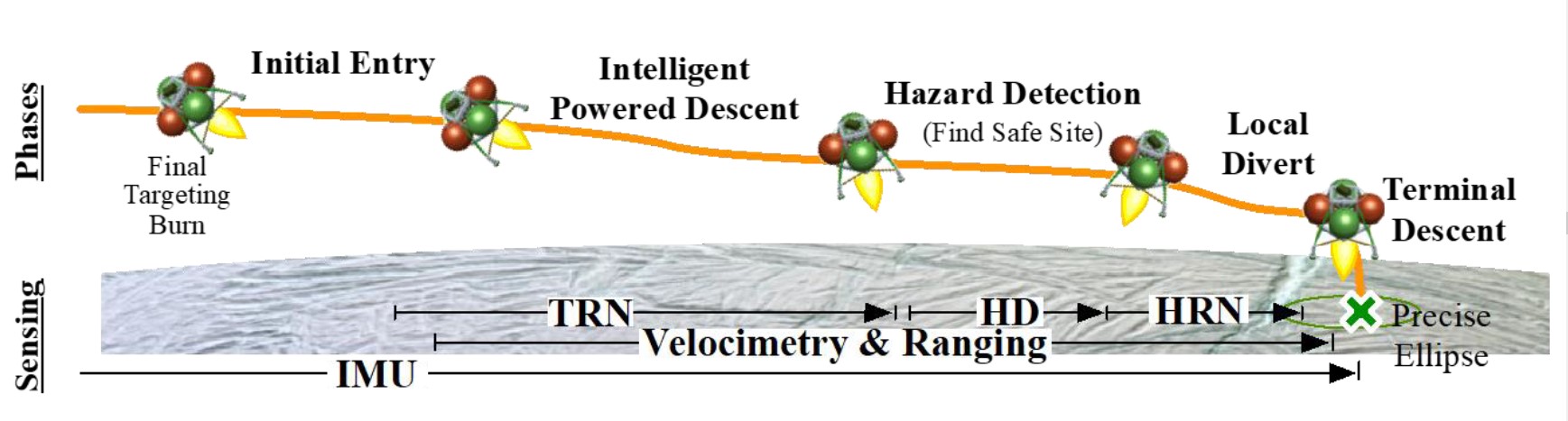
The navigation doppler LiDAR (NDL) activates at about 4 miles (6.4 km) above the surface. The NDL provides information about the lander’s velocity and altitude, helping to increase the precision of the guidance and navigation algorithms on the DLC. Before developing the NDL system, landers on the Moon and Mars relied on radar systems to measure velocity and altitude. The radar-based systems were larger, heavier, more power-hungry, and much less precise than the LiDAR-based NDL system.
During the final moments of the descent, the lander rotates to a vertical orientation for a soft landing. At about 1,600 feet (500 m) above the surface, the hazard detection LiDAR (HDL) activates, taking a detailed image of the surface and immediately creating a detailed three-dimensional (3D) map of the landing zone. The HDL sends out a series of rapid (nanosecond) laser pulses toward the surface, and a photosensor measures the return time, called the time of flight (ToF). The distance to the surface is calculated using half of the ToF multiplied by about 30 cm/ns (the speed of light).
Millions of ToF measurements are combined to produce a point cloud. Image processing software in the DLC uses the point cloud data to create a 3D map of the landing zone. The DLC then uses that 3D map to locate smaller hazards, such as too steep slopes or too large rocks, and identifies safe landing sites within a 330-foot (100 m) diameter circular final landing zone. There are still some unknowns about the use of LiDAR on the Moon. If the material on the ground in the landing zone is not reflective enough, the return signal will be weak. Work is still underway to reduce those uncertainties before Artemis takes off for the moon.
New Shepard testbed
Blue Origin’s New Shepard rocket, not the crew capsule, is being used as a testbed for various SPLICE components. The capsule does not use an automated system; it deploys an initial set of parachutes to slow its speed, then another set of three larger parachutes to carry the land the capsule softly at about 15 miles per hour. When the capsule separates from the New Shepard rocket during the flight, the SPLICE test begins.
New Shepard uses its own automated system for the actual landing, but the SPLICE components are activated just like they will be used on an Artemis mission. The TRN uses stored surface image data to identify features and hazards during descent. The NDL gathers data about the location and velocity of the New Shepard. The data from these and other sensors are fed into a prototype of the DLC. In addition to testing the various sensor suites, the flights on the New Shepard are designed to identify the computational power needed to support full SPLICE operation and integration into Artemis. The exact partitioning of computing tasks between the DLC and the primary flight computer is still being determined to optimize (minimize) the size, weight, and power consumption of the DLC while not overloading the primary flight computer.
Navigation Doppler LiDAR
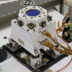
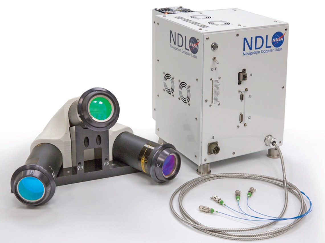
The NDL provides ultra-precise velocity and range measurements 20 times per second for three laser beams and is fed into the guidance computer. NDL measurements are used in the lander guidance, navigation, and control (GN&C) subsystem to minimize navigation error in velocity and position (minimizing the landing ellipse size) and control vertical and lateral trajectories during the final descent tightly. The NDL engineering test unit (ETU) includes an optical head housing three fiber-coupled telescopes and the electronics chassis (Figure 2). When integrated into Artemis, the three telescopes can be separated as needed to optimize the design of the spacecraft. The NDL ETU telescope head weight is about 2 kg, and the electronics chassis weighs about 10.9 kg and measures 37 x 25 x 18 cm. The system consumes an average of 77 W of power. It is designed to achieve line-of-sight velocity and range performance of +/-215 m/s and 7+ km, respectively, with accuracies on the order of 2 cm/s and 2 m, respectively.
Hazard detection LiDAR
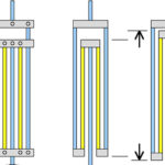
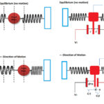
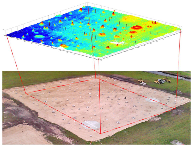
The HDL is a scan-array LiDAR that integrates an optical beam steering mechanism with a detector array to produce a precise three-dimensional terrain map within seconds. It includes a combined electronics-photonics box along with a fiber-coupled optical head. A telescope and two spinning Risley prisms are in the optical head. Risley prisms are pairs of wedge prisms that can be used to continuously scan an optical beam of a moderately large aperture over a wide angular range. In the telescope head, the Risley prisms are controlled to a specified scan pattern to maximize over-sampling of ground pixels to eliminate mapping gaps. When operating from a 500-meter range and a near-vertical descent, the HDL generates a 100-meter-diameter circular map in 2 seconds with a 5-cm ground distance and a range precision of 1 cm (Figure 3). The HDL can be operated at multiple ranges during descent for use in other precision landings and hazard avoidance (PL&HA) functions such as early site evaluation, map updates to TRN, rendezvous and docking/berthing with other spacecraft, as well as proximity navigation, contact, and retrieval missions to smaller bodies. The surface data can also provide high-resolution maps and intensity images to guide mission science and plan ground operations.
Summary
The SPLICE system will enable automated moon landings for the Artemis spacecraft. It consists of several subsystems, including the navigation Doppler LiDAR, terrain relative navigation, hazard detection LiDAR, and the descent and landing computer. Blue Origin’s New Shepard rocket is being used as a testbed for the subsystems and to help determine the optimal partitioning of computing tasks between the descent and landing computer and the primary flight computer.
Check out Executive Editor Lee Teschler’s video recap of APEC 2022 where he covered a plenary session by NASA Principal Technologist John Scott where he discussed the power electronics behind the NASA Artemis project.
References
Game Changing Development SPLICE: Safe and Precise Landing— Integrated Capabilities Evolution, NASA
NASA Lunar Lander Reference Design, NASA
NASA SPLICE Project: Developing the Next Generation Hazard Detection System, NASA
The SPLICE Project: Safe and Precise Landing Technology Development and Testing, AIAA Scitech 2021 Forum