by Eileen Otto, Marketing Manager, Macro Sensors
The abundance of shale gas has increased the demand for gas turbines throughout the world. To address demand, gas turbine manufacturers are not only building more turbines but also designing them to operate more efficiently. Controlling valve performance is essential for improved turbine efficiencies. As valves regulate the flow of fuel throughout the different components of a gas turbine, the accurate monitoring and controlling of flow from these valves enable turbines to operate more efficiently with minimal wasted energy.
Gas turbines incorporate a variety of control valves inlet guide vanes, transfer valves, gate valves, bleed valves, and so on. Each performs a different operation, for example, bleed valves “bleed” off small quantities of fuel, while gate valves permit or prevent gas flow, but are typically not used for regulating flow. The proper opening and closing of these valves depend on the plant control schemes.

Typically, gas turbine power plants operate under a highly developed control algorithm. Plant operators, therefore, need to know the position of valves at all times to ensure proper operation. Though many valve users may only need to know if a valve is open or closed, some operators need to know the exact position in their application. For instance, as bleed valves are modulating valves, they should be opened a specified amount, depending on how much power is being generated. By ensuring valves are properly opened or closed to the right degree, plants operate more efficiently. For a medium-sized plant, a 2% efficiency improvement could translate into a million dollars in fuel savings.
Though actuators move the valves, feedback devices translate valve position back to turbine control systems, indicating “if” and “how much” a valve is opened or closed. LVDT (Linear variable differential transformer) sensors serve as the position feedback device that provides valve position measurements to ensure proper turbine operations. Constructed of stainless steel and rated UL and ATEX for operation in high temperatures and harsh and potentially explosive environments, these sensors convert the rectilinear motion of an object, to which it is coupled mechanically, into a corresponding electrical signal that is used by a programmable logic controller as part of a control system.
Mounted redundantly either in two or three sensor groups on actuators that move the gate of a gate valve or ball/butterfly of a rotating valve, the sensors “tell” the turbine control system how far a valve is “open” or “closed” to a certain proportion. Using this position feedback, the control system determines if more or less fuel is required for proper turbine operations and signals actuators to move the gate, ball or butterfly to make the necessary valve adjustments. When the actuator begins to move a valve, a corresponding sensor sends an analog electrical signal, proportional to the amount of valve displacement to the control system. With sensor feedback provided in real-time, the actuator can continually be adjusted until the desired opening is reached.
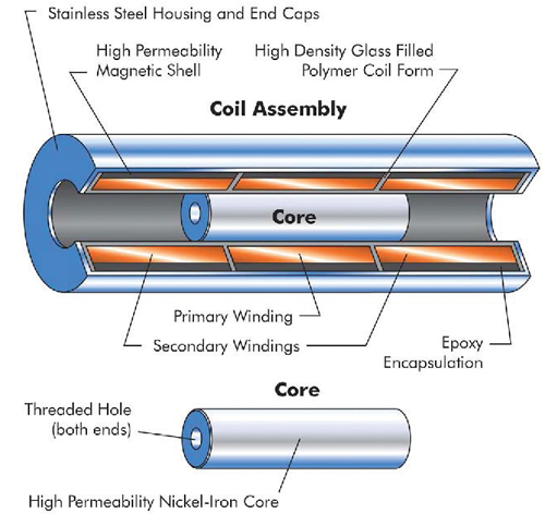
As simple devices with only a few coils of wire and a ferrous core, LVDTs can withstand high levels of shock and vibration, get extremely dirty and still operate according to their specifications. The ability to separate LVDT electronics, which are located in the turbine control system, from the coils is one of the main reasons that these sensors can survive so well in power plants. With electronics remotely located, an LVDT can withstand high temperatures of 350 to 400° F on the turbine.
As gaseous vapors are present in gas turbines, LVDTs installed on turbines must meet safety parameters and be approved by certified agencies such as UL, FM, CSA and ATEX. These requirements set a standard for sensor design based on the environment called an “ignition curve.” Designed with an inductance below the ignition curve, the sensor in standard operation or in a fault condition never has enough power to ignite any gaseous vapors present.
LVDT technology uses the transformer principle to measure linear displacement in gas turbines. A primary coil is excited with an ac signal. The ferrous core ac couples that signal onto two secondary coils that are wound 180° out of phase. If the core is centered between the two secondary coils, the voltage is coupled equally on each secondary. However, since the second rate is out of phase, the output, when the secondary coils are added together, is zero. If the core is positioned to couple more voltage onto one secondary than the other, the output increases linearly proportional to the amount the core was displaced.
When attached to a gate valve in a redundant configuration, the sensors give an unusual output. LVDTs, by nature, have a null position that produces a 0 Vac output. Since turbine valves were designed so long ago, engineers used techniques that do not have the sensor go through zero because the turbine control system would not know if the core was at the zero position or if there was a failure. To combat this problem, a tap is taken off of the primary coil and that voltage is added to the secondary output. This shifts the output so that the voltage is always positioned anywhere over the linear range of the sensor.
Development of new winding techniques, such as computerized layer winding, and improved micro processing have considerably reduced the length of the linear position sensor body compared to its measurable stroke length.
Macro Sensors
www.macrosensors.com