by Ted Tomita, Global Product Marketing Manager, Honeywell Sensing & Productivity Solutions
Everything from an excavator to a thermostat is getting smarter and the demand for more intelligent and connected systems is driving more demand for sensors in nearly every industry. A report by market research firm BCC Research anticipates the sensor market will grow by more than 10% by 2020.
Implementing more sensors into a system may bring more value to a customer through data, but it may also introduce more variables that could cause a system to fail. A faulty sensor that is unreliable or inaccurate may be costly to replace, difficult to troubleshoot and even impact an end user’s operation. Choosing a sensor that performs reliably and accurately is crucial to protecting both OEMs and end users from potential system failures. But how can an engineer confidently assess and choose the right sensor for their system?
Industry standards have helped set expectations for performance and reliability for today’s sensors. Understanding these standards can help engineers specify a sensor that meets the needs of their systems, and ensure that the overall system will meet customer expectations. In the transportation industry, standards serve an especially important role as they influence sensor qualities related to environmental sealing, noise immunity, temperature range and vibration.

Let’s examine these four standards and how each can affect an OEM and design engineer.
Environmental sealing
Environmental sealing refers to a sensor’s ingress protection against water and dust while in operation. A key standard engineers should be aware of is the Ingress Protection (IP) rating published by the International Electrotechnical Commission. The highest rating a sensor can achieve is IP69K under the IP standard ratings. The IP69K test specification was initially developed for road vehicles, especially those that need regular intensive cleaning (dump trucks, cement mixers and so on) The first number indicates the sensor’s solid particle protection from a range of 0 to 6, with 6 indicating that the sensor is completely dust tight. The second number indicates the sensor’s water protection rating from a range of 0 to 9K, with 9K indicating that the sensor is protected against close-range, high-pressure, high-temperature spray downs.
For example, an engineer who is specifying sensors for a combine harvester may refer to these ratings to ensure the sensor he or she uses can withstand potential dust and soil exposure in a field, and water protection from a power washer that could be used to clean the equipment.
Engineers can refer to these standards to ensure they will not require designing additional protection layers for the sensor. For instance, an engineer may unnecessarily design additional O-rings to protect an excavator’s sensors against water exposure if he or she is not aware that the sensors are already rated 9K and protected from such environments.
Electrical noise immunity
Electrical noise immunity and electromagnetic compatibility (EMC) are among the most important standards in the industry today. Every cell phone, radio tower and wireless device emits electrical noise and the interference is becoming more pervasive as consumer devices become smarter and more connected.
Implementing a sensor that falls short in or lacks electrical noise immunity may cause sensor failures that are often difficult to diagnosis. In a real-life example, an executive at a car manufacturer decided to take the company’s new prototype vehicle to the airport where he received a phone call as he arrived. At the moment the call came in, the car’s engine immediately stalled, then fired-up again when the call ended. After rounds of testing and weeks of investigation, the engineering team found that the electrical noise from the airport combined with the cell phone exceeded the noise immunity in the engine’s feedback loop sensor causing it to fail and the entire engine to stop.
When looking to protect sensors from similar electrical noise failures, engineers should look for noise immunity ratings, which are typically measured in volts per meter. Many sensors used in transportation vehicles have traditionally been rated at 60 V/m. However, electrical noise immunity is not expected to decrease over time and the industry is moving toward ratings of 100 to 200 V/m.
In addition to reviewing a sensor’s volts-per-meter rating, vehicle engineers should also be aware of ISO ratings that indicate a sensor’s electromagnetic compatibility. There are seven ISO ratings to meet industry standards for vehicles ranging from passenger vehicles to agricultural and forestry machinery.
Engineers can find it difficult to troubleshoot their systems for complications due to electrical noise. Additionally, a machine that is rendered inoperable may be costly to an end user if it’s necessary for daily production. Being aware of current and future trends in noise immunity standards can help future- proof systems and vehicles from potential failures in the future.
Temperature
There are no specific organizations that standardize a temperature range in sensors. However, most sensor manufacturers adhere to industry norms. For example, most commercial products use sensors with a temperature range of -20° to 85° F. This is the temperature threshold in which the sensor can safely and accurately operate without damaging the component.
A sensor’s temperature range may change from industry to industry. For example, in the transportation industry, a broader temperature range of -40° to 150° F is more common and necessary, especially for applications in engines and transmissions. A wider temperature range provides greater protection against equipment failure no matter what environment the sensor is operating in, and also offers more flexibility in where to install the sensor. For example, an excavator could be used in the middle of the Australian Outback for a tunnel construction where temperatures can be high.
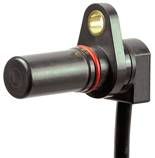
A sensor may be damaged or its accuracy could deteriorate if it is exposed to temperatures beyond its threshold. For example, quadrature speed sensors use magnets and Hall ICs to detect speed and direction of a rotating gear. These sensors are commonly installed in hydraulic pumps and electric motors that provide mechanical power to forklift trucks, construction equipment and agriculture equipment. The magnet in the sensor could be degraded when exposed to temperatures beyond its threshold, leading to reduced sensor performance.
Similar to environmental sealing, OEMs can design additional protection to guard the sensor from being exposed to extreme heat or cold. However, these provisions may be costly and require additional time and testing. Choosing the right sensor that meets the system’s needs can help save design engineers both time and cost.
Vibration
Vibration conditions may not seem problematic for sensors, but vibrations may cause the overall machine problems if the component is not designed to withstand them. Heavy machines experience significant vibration because of off-road travel and running large diesel engines where sensors are in sub-systems, such as hydraulic pumps, actuators and electric motors, among other locations. Sensors that lack the necessary robustness to withstand constant or random vibrations may send false signals to the operator or experience critical failure that can damage or hinder the overall machine.
There are two vibration types that design engineers should consider: high frequency and random. High-frequency vibration is commonly found in applications where the machine is running a large diesel engine. An important standard for these conditions is MIL-STD-202-204 Test Condition D, a standard established by the Dept. of Defense. It’s among the most stringent vibration standards for the heavy machinery industry. Sensors that meet this standard ensure the component can operate under such environments without worry of failure.
Random vibration conditions, on the other hand, are common for equipment that regularly moves in off-road conditions, construction sites and other rough terrain. For these applications, sensors should meet another DOD established standard called MIL-STD-202-214 Test Condition I. This standard ensures that the sensor can operate accurately under vibration conditions that affect its entire physical plain, whether from the bottom or side of the sensor.
Machines are getting smarter and using more sensors. It’s unlikely that this trend will reverse any time soon. Engineers in all industries will feel more pressure to specify reliable and accurate sensors that can withstand their system’s daily rigors and harsh environments. Making an informed decision starts with reliable information, and sensor standards offer the best benchmark for engineers. Using this knowledge effectively can help deliver reliable performance and increased value to customers.
Honeywell Sensing & Productivity Solutions
www.sensing.honeywell.com