by Brent Evanger, Banner Engineering, Sr. Application Engineer—Vision Sensors
When an inspection application requires more sophisticated data acquisition than that provided by a traditional photoelectric sensor, many application engineers will choose a vision system. Through it, they can obtain image-based data and identify label orientation, part presence and arrangement, and other features. But for some of these applications, a full vision system may not be required. Instead, you can use a compact touch screen image sensor with no PC or additional electronics required.

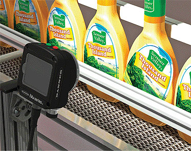
Label Orientation: The touch screen image sensor lets you set inspection parameters on the spot, and then examine a target object, such as a salad dressing bottle, to verify label placement and orientation.
A touch screen image sensor can combine the capabilities of three separate sensors into one housing. One sensor is a match sensor. It compares the target object to a stored reference point, identifying parts of irregular shape, alphanumeric characters, etchings and labels at rapid production speeds. An area sensor identifies target features within a region of interest, ideal for detecting drilled holes on a metallic component or inspecting blister packs, and verifies that all
features are correctly sized and located. The third sensor has a similar purpose—examining an area for specific features—but offers tools that adjust for motion.

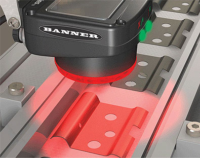
Drilled Hole Inspection: The image sensor features integrated lighting to create contrast between target features (drilled holes) and their background (metal plates), allowing any reject parts to be readily identified.
These tools allow the sensor to detect objects of varying position and orientation on the production line. The image sensor also incorporates integrated lighting and adjustable lenses to optimize image contrast, as well as accommodate changing plant conditions.

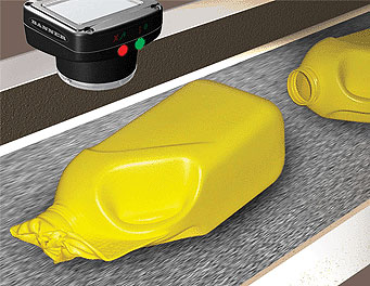
Injection Molding Verification: Once the sensor is programmed, it compares the obtained image—in this case, a plastic container—to a reference pattern, confirming its size and shape match the parameters set. If the target object fails this inspection, it is rejected from the production line.
The sensor’s touch screen LCD display is used for setting up an inspection and modifying parameters. Once you select the sensor type (match, area, or area with motion), it captures a sample image. From this point, you configure the sensor by adjusting the region of interest, setting inspection parameters, and designating the minimum and maximum pass count. The final setup configuration and logged inspection results can be downloaded from the sensor to a USB drive through the sensor’s USB port. To minimize system downtime, you can set new application parameters offline through the sensor’s software emulator, and then upload these new configurations onto the sensor using the USB drive.
Banner Engineering
www.bannerengineering.com
