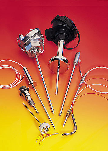
Analyze the RTD’s strengths and weaknesses with respect to the application before making a selection. The application ultimately determines the RTD’s specifications. Watlow’s RTD sensors are designed to ensure precise and repeatable measurements as well as meet environmental requirements for each application. A high signal-to-noise ratio output increases the accuracy of data transmission and permits greater distances between the sensor and the measuring equipment. These resistance-wire RTDs have a positive temperature coefficient; the resistance change is proportional to the temperature measured.

Resistance Temperature Detectors (RTD) typically operate within a broad temperature range of -200°C to +850°C, are fairly linear, and have excellent long-term stability. Unlike thermocouples, cold junction compensation is not needed, and their temperature range and linearity are superior to both thermistors and thermocouples. When applied correctly, RTDs exhibit extremely low drift, so they do not require recalibration. On the other hand, their comparative weaknesses include lower sensitivity, slower response time, and susceptibility to self-heating. All these qualities make them application-specific.
Principle of operation
RTDs are passive components that require an excitation current to produce an output signal. Similar to thermistors, their resistance “varies” in direct proportion to changes in temperature. The temperature-sensitive element is made of metal or a metal alloy, which gives them the positive temperature coefficient.
Platinum, gold, silver, tungsten, nickel, and copper have been successfully used in different RTD devices, however, platinum is superior to the other metals. It has the highest resistivity, 59 ohms per circular mil foot (Ω/cmf), a wide temperature range, good linearity, and low long-term drift. Nickel or nickel alloy RTDs are more economical but have a narrower temperature range, poorer linearity, and a greater long-term drift.
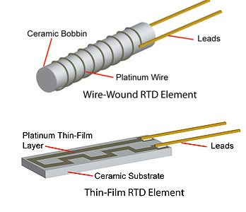
There are two major types of RTDs: wire-wound and thin film and each have some advantages and disadvantages. For example, a typical wire-wound RTD uses platinum wire wound around a ceramic or glass bobbin in one of two configurations: birdcage and helix. The birdcage winding construction keeps the platinum wire loose and lets it expand and contract freely with a change in temperature. This minimizes long-term stress-induced resistance change, but has very poor resistance to vibration and is primarily limited to lab use. In a sealed helix-constructed, wire-wound RTD, the bifilar winding is wound around the bobbin and then sealed with molten glass, ceramic cement, or another high-temperature, non-conductive coating. This construction helps protect the wire from vibration, but it is prone to long-term stress-induced resistance change when the bobbin and platinum wire have different temperature coefficients of expansion.

In the simplest wire-wound RTD construction (top), thin platinum wire is wound around an insulator bobbin. The wire ends are spot welded or high-temperature soldered to the lead wires. A non-conductive protection coat with good thermal transfer properties covers the whole RTD element assembly. In the thin-film type, the sensing element is formed by depositing a thin layer of platinum onto a ceramic substrate and attaching the leads to the connecting pads. A glass coat (not shown) encapsulates the element.
Newer thin-film type RTDs are made by depositing platinum or another metal alloy film onto a substrate, etching the shape of the resistive element, and then sealing the sensor. The thin film devices are smaller, faster, and considerably less expensive than the wire-wound parts. Thin-film platinum RTDs have virtually linear resistance versus temperature curves and provide a low cost alternative to high-accuracy, wire-wound devices. The drawbacks of film-type RTDs include poor long-term stability and narrower temperature range.
The RTD temperature coefficient represents the sensors’ sensitivity to temperature change. The larger the temperature coefficient (α), the larger the resistance change (ΔR) in response to an ambient temperature change (ΔT):
ΔR = αRo ΔT,
Where:
α = temperature coefficient, Ω/Ω/°C
Ro = nominal sensor resistance at 0°C, Ω
ΔT = temperature change from 0°C, °C
According to the DIN 43760 standard, the resistance-temperature coefficient of platinum wire typically used in RTD manufacturing is 0.00385 Ω/Ω/°C at 0°C. Another frequently mentioned value, 0.00392 Ω/Ω/°C at 0°C, is the resistance-temperature coefficient of chemically pure platinum wire used for standards. To illustrate using the equation above, consider an ideal 100 Ω RTD that has a resistance of 100.000 Ω at 0°C. Therefore, at +1°C the RTD resistance will be:
RT = [Ro + (αRoΔT)] = 100 + (0.00385)(100)(1) = 100.385 Ω.
A problem here is that the RTD temperature coefficient changes over the temperature range, so to obtain an accurate value at any given temperature, a curve-fitting process is required. Use the Callender-Van Dusen equation to calculate the RTD resistance over the entire temperature range:
RT = Ro + Ro α [T – δ(T/100 – 1) (T/100) – β(T/100 – 1)(T/100)3]
Where:
RT = resistance at temperature T, Ω
Ro = nominal RTD resistance at 0oC, Ω
α = temperature coefficient, Ω/Ω/oC
δ = 1.49 for pure platinum
β = 0 if T > 0
β = 0.11 if T < 0
Excitation current vs. resistance
Because RTDs are resistors, they need an excitation current to produce an output voltage. At a given current value, an RTD with higher resistance will have higher voltage resulting in lower required amplification and higher signal-to-noise ratio. However, increasing the RTD’s resistance considerably slows its response, which might be unacceptable for many measurements.
 An RTD does not produce any voltage by itself. A source of voltage and an excitation resistor, Rex are needed to make the RTD work. The excitation resistor and the RTD form a voltage divider. Voltage drop across the RTD is proportional to its resistance, so when RTD resistance changes with temperature, the change in voltage represents the change in temperature.
Selecting a low-resistance RTD for remote sensor installations can also present a problem. Long lead wires can add significant error to the temperature measurement. For example, if an RTD with a nominal resistance of 100 Ω is installed at a distance of 200 ft from the signal conditioning circuit, and the two lead wires are made of 24 AWG stranded (7 strands) tinned copper wire, the output voltage seen by the voltmeter will be the sum of the voltage drops across the RTD and both lead wires.
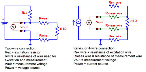
The wire selected for this example has a resistance of 0.023Ω/ft, so the total wire resistance is calculated as: Rwire = (0.023)(200 + 200) = 9.2 Ω. The total RTD resistance plus the wire resistance is 109.2 Ω, which adds a 9% error to the measurement. The problem stems from the fact that the same two wires are used to supply the excitation current and make the measurement. To make matters worse, copper resistance changes with temperature, making compensation difficult. Therefore, to obtain an accurate temperature reading, the excitation current wires and the measuring connection wires are separated in a 4-wire, Kelvin connection. One pair of wires supplies constant excitation current, while the other pair connects the voltmeter (or signal conditioning circuit) directly across the RTD. Here, the wire resistance does not affect the voltage drop across the RTD, because the excitation current is constant, and the resistance of the measurement wires has no effect on accuracy since it is negligible compared to the high input impedance of the voltmeter.

One pair of wires in a two-wire connection supplies both the excitation current and measures the RTD output, so the voltage drop due to the resistance of the excitation current lead wires can add a significant error to the output signal. On the other hand, the four-wire or Kelvin connection separates the excitation and measurement wires. Here, the excitation current flows only through the RTD and excitation wires and the voltage drop does not appear in the measured variable. This makes the measurement more
accurate, even in remote installations.
A compromise between the 2-wire and the 4-wire connection is the most widely used 3-wire connection. One end of the RTD connects to one wire, and the other end connects to two wires: a wire for power and a wire for signal.
Another frequently used circuit that avoids the effect of lead-wire resistance on the accuracy of a measurement is a four-resistor Wheatstone bridge. Two lead wires apply excitation power to the bridge. The bridge output is connected to a voltmeter, an operational or instrumentation amplifier, or a high-resolution analog to a digital converter. Ideally, the three bridge resistors should have a zero temperature coefficient, so only the RTD resistance depends on temperature. The output voltage depends only on the bridge resistance unbalance — it is not affected by the resistance of the lead wires.
 The Wheatstone Bridge circuit using an RTD is similar to the circuit used with thermistors. The values and temperature coefficients of resistors R1, R2, and R3 should be selected in accordance with the accuracy needed for the application.
When selecting the RTD resistance and the excitation current, maintain a balance between the resolution and response time. It might be tempting to select a low resistance RTD for faster response, but since Vout = (RRTD)(Iex), a lower resistance requires higher excitation current to maintain the same output voltage and high system resolution. Higher excitation current generates more heat and raises the sensor temperature above the temperature of the object being measured, which produces a significant error. As a rule, the excitation current should be kept as low as possible to reduce the self-heating error. Typically, self-heating errors can be kept below 0.5°C, which is considered acceptable.
Another measurement error, thermal shunting, might creep in when measuring the temperature of a small object. Due to its relatively large size, the RTD might act as a heat sink and alter the temperature of an object that is similar in size or smaller than the sensor itself.
Maintenance
Interchangeability is critical when replacing worn or failed RTD elements. Knowing the allowed variance of readings between two sensors, allows equipment maintenance without recalibration. The American Society for Testing and Materials (ASTM), American Scientific Apparatus Manufacturers Association (SAMA), International Electrotechnical Commission (IEC), and Japanese Standard (JIS) have all developed several standards for platinum RTD elements. These standards guarantee element interchangeability when used within the specified temperature range.
For example, European standards IEC751 and DIN 43760 contain identical accuracy and tolerance parameters. They are collectively referred to as DIN IEC 60751, or just IEC751 and specify resistance values at various temperatures for platinum RTD sensors. Standard compliant devices have a resistance of 100.00Ω at 0°C and a temperature coefficient of resistance of 0.00385 Ω/Ω/°C from 0°C to 100°C. Specified overall temperature range and tolerance depend on the class.
The most accurate, DIN Class A has a ±0.06% tolerance at 0°C that spreads to ±0.24% at -200°C and ±0.46% at 650°C. DIN Class B has a ±0.12% tolerance at 0°C with a wider spread of ±0.56% at -200°C and ±1.34% at 850°C. Manufacturers frequently express tolerance specifications in Ω or in °C instead of %.
Most American and European manufacturers produce Class A and B IEC751-compatible elements. In addition, some RTD manufacturers offer less accurate class C and D elements with a ±0.2% and a ±0.5% tolerance at 0°C, respectively.
Most Japanese and some American manufacturers use Japanese Standard JIS C 1604. This standard specifies the same base resistance of 100.00Ω at 0°C, a temperature range of –200 to +650°C, and tolerances as IEC751, except the temperature coefficient of resistance is 0.003916 Ω/Ω/°C. JIS C 1604 J and K standard tolerance classes correspond to the A and B classes of the European standard.
The environment
Many industrial and some lab applications require the RTD element to be protected from the environment. Moisture, corrosive environments, mechanical impact, and vibration can quickly degrade the sensor if not taken into consideration. Selecting the type of RTD or RTD probe appropriate for the application and compatible with the environment is the key for reliable service.
RTDs for industrial applications are typically built into a probe with a stainless steel or Inconel sheath protecting the sensing element from the environment and mechanical impact. This protection allows the measuring end of the probe to be inserted directly into the measurement area. Termination wires or a connector installed on the opposite end connect probes to the measuring instrument.
Low-temperature range, thin-film RTD probes are typically safe to use in the -40°C to +200°C range. Low-temperature range wire-wound probes extend further into the -200°C to +200°C range. Inside the probe, the RTD element uses silver-plated copper lead wires with plastic insulation, such as Teflon® rated at 260 °C. By comparison, fiberglass insulation is usable up to 480 °C, while PVC insulated wires are limited to only 105 °C. Other considerations include:
- Welding — the preferred method of wire termination.
- Empty space inside the probe is typically packed with aluminum oxide powder that has good heat-transfer characteristics and acts as a shock and vibration absorber.
- To protect the element from moisture, the probe is sealed on the lead-wire side using epoxy or other potting compounds.
High-temperature probes designed to work in the -200°C to +600°C range typically have internal lead wires made of nickel held in place with magnesium oxide insulators. Empty space inside the probe is typically packed with magnesium oxide powder, and the lead-wire end is sealed with epoxy. In both designs, the lead wires are connected in a 2-wire, 3-wire, or 4-wire configuration and are brought out with several options of insulated wires, terminated wires, and male and female connectors.
Surface, gas, and liquid measurements require different sensor configurations. Probes most suitable for liquid measurements are typically encased in a stainless steel sheath that has excellent corrosion resistance. Inconel sheaths provide superior protection against corrosion and oxidation at high temperatures. Outside diameters are typically 1/8 in., 3/16 in., ¼ in., and 3/8 in.
Surface sensors vary greatly depending on application and method of attachment. They can be touched, screwed, bolted, or glued to the measured surface. Gas and air measurements require free access of the gas to the RTD element to facilitate the heat transfer.
Certain precautions should be observed during installation and operation. RTDs, especially the wire-wound type, are susceptible to mechanical damage and should be installed with care and protected during use. In addition, minimizing mechanical and thermal stresses is essential for long service life. Electromagnetic interference can be a serious problem because the signal level is quite low. Use proper shielding and twisted-pair wires to keep electrical noise at an acceptable level. Increasing the gauge of lead wires minimizes their resistance, which is especially important for minimizing measurement error in two-wire RTD connections.
For more information:
Omega Engineering, Inc.
http://www.omega.com
Thermo Sensors Corp. (TSC)
http://www.thermosensors.com
U.S. Sensor Corp.
http://www.ussensor.com
JUMO Process Control, Inc.
http://www.jumoplus.com
Watlow Electric Manufacturing Co.
http://www.watlow.com
Pyromation, Inc.
http://www.pyromation.com
Minco
http://www.minco.com

It is a great article. However, I would like you write another article about chips currently on the market that condition, process the RTD signal and delivers the data already for MCU.
Dear sir
Have nice day, just i can say you , it is interesting for me , can i have update information , because i like this subject.
Dear sir,
I have read your article and I think it’s very interesting, I would publish on book that I’m writing one of his pictures (june-sens2) , can I have your consent?
Kind regards
S. G.
can u suggest me the circuit design of signal conditioning circuit using RTD???