By John R. Gyorki
Editorial Director
Semiconductor temperature sensors are easy to use if you do your homework when matching the sensor with the application.
Temperature sensors are designed into every heating, ventilation, and air conditioning system. Automotive systems rely on temperature sensors for engine control. Many industrial processes require highly accurate and stable temperature measurements. Today’s computers and portable electronic devices have extremely high circuit density with no easy way for heat removal, which makes temperature monitoring a must.
All temperature sensor applications fall into the temperature measurement or thermal management category. The most widely used types of temperature sensors are thermocouples, resistance temperature detectors (RTDs), thermistors, and semiconductor temperature sensors.
Thermocouples are known for their wide temperature range and low drift. RTDs have the highest accuracy and stability, and good linearity. Thermistors are fast and have high sensitivity. However, all these sensors require a modest amount of interface circuitry and are difficult to use. Relative newcomers, semiconductor temperature sensors offer several benefits that other sensors cannot match.
Though their temperature range of -50oC to +150oC is rather limited, semiconductor temperature sensors have several valuable features such as excellent linearity, high sensitivity, and extremely small size. They are inexpensive; require no linearization, cold junction compensation, or signal conditioning; often combine several functions on one chip; and produce analog, logic, or digital outputs that can be interfaced directly to an analog measurement circuit, an analog-to-digital converter (ADC), a microprocessor, or a fan control. Measurement-system noise immunity is superior to other sensors since the output is already amplified or digitized inside the integrated circuit (IC).
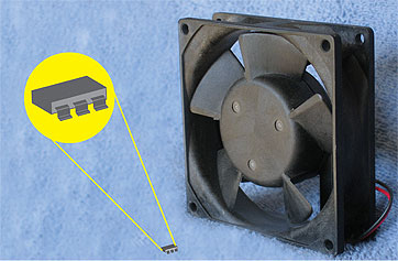
Thanks to their small size, semiconductor sensors can be installed directly on PC boards, heat sinks, underneath high-power integrated circuits, and in small portable electronic devices. Typical applications include the fastest growing types of consumer products such as cell phones, PCs, PDAs, MP3 players, and automotive systems.
The sensing element
A semiconductor temperature sensor is an IC that combines a temperature-sensing element with signal conditioning, output, and other types of circuitry on one chip. It relies on the change of voltage across a p-n junction, essentially a silicon diode, in response to a temperature change to determine the ambient temperature. The bipolar IC substrate is designed to build p-n-p and n-p-n transistors, so in practice, the sensing diode is usually formed using a transistor with the base and collector shorted. The following equation shows the effect of temperature on the forward voltage of a silicon p-n junction:
VBE = VG0 (1-T/T0) + VBE0(T/T0) + (ηKT/q) ln (T0/T) + (KT/q) ln (IC/IC0)
Where:
T = temperature, oK (Kelvin)
T0 = reference temperature, oK
VG0 = bandgap voltage at absolute zero, V
VBE0 = forward voltage at current IC0 and temperature T0, V
K = Boltzmann constant, J/oK
q = charge of an electron, C
η = constant associated with a specific device
IC = forward current at temperature T, A
IC0 = forward current at reference temperature T0, A
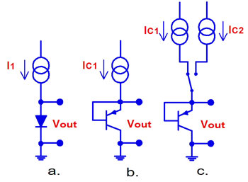
However, determining temperature using this equation is not very practical since the voltage depends not only on the temperature, but also on the current and the device properties. To eliminate the effect of these variables, practical circuits switch the diode alternately to two constant current sources and determine the temperature based on the difference between the two forward voltages or their ratio:
Δ VBE = (KT/q) ln (IC1/IC2)
Where:
IC1 = forward current from first current source, A
IC2 = forward current from second current source, A
Frequently IC2 is selected to be 10 times greater than IC1. In this case, the thermal coefficient of the sensing element is approximately 200 µV/ oC.
Sensor types
Semiconductor temperature sensors come in three types determined by the output signal they produce: analog, logic, and digital. They also measure temperature in one of two ways: internally or remotely. When the measuring diode-connected transistor is built on the sensor IC substrate, the sensor measures the temperature of its own body. Sensors that have no measuring diode built-in connect to a remotely mounted sensing diode-connected transistor.
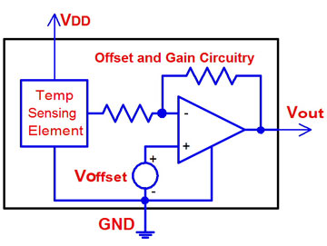
Analog Voltage and Current Output Sensors: The oldest type, analog output semiconductor temperature sensors, generates output voltage or current proportional to sensed temperature. They combine the sensing diode with the offset and amplification circuitry on one chip. The offset is needed because the output signal of the sensing diode is proportional to absolute temperature, oK. Since oC and oF scales are more common than oK, the signal needs to be offset to the new zero oC or zero oF point. Additional offset is needed to allow measuring negative temperature without using a negative power supply.
Since the voltage across the sensing diode changes only 200 µV per oC an internal amplifier is needed to boost the output signal in order to increase the system noise immunity. This makes the voltage output compatible with most analog temperature measuring and monitoring systems. Industrial applications that have high levels of electrical noise use current output IC sensors where output current is proportional to the measured temperature.
Logic Output Sensors: Many temperature control applications do not need to know what the current temperature is until it reaches a preset level–when some action needs to be taken. Logic output sensors designed for this type of applications work like a thermostat in our homes. In fact, these sensors are commonly referred to as thermostat sensors. They do not output the temperature value, but instead one or several logic outputs change their state when temperature exceeds (“hot” sensors) the preset value, or drops below (“cold” sensors) it.
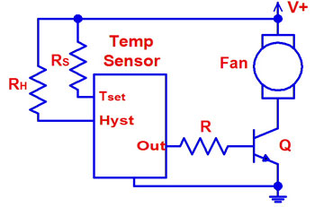
Some devices have user-programmable trip temperature and hysteresis, which is needed to prevent chatter. The programming is usually done with resistors. Yet other devices have both the temperature and the hysteresis fixed. Logic temperature sensors are simple, inexpensive and are extremely easy to use. Typical applications include turning on fans and alarms, or setting an interrupt to signal the processor that the temperature limit has been exceeded.
Digital or Serial Output Sensors: A digital temperature sensor is really an analog sensor that contains an ADC and a serial output port. Sensor output options include an I2C, SMBus, or SPI interface that connects directly to a compatible microprocessor/microcontroller interface or a pulse-width modulation (PWM) output. In addition, many sensors have one or several comparators that drive either logic, open collector, or open drain outputs. These outputs are typically wired as an
interrupt for the microcontroller, an on/off line for a fan or alarm, or a hardware power shut-off control signal.
Digital sensors using the single-wire PWM format vary the ratio of high time to low time (duty cycle) of a square wave to represent the temperature value. The processor counts the duration of the high and low times and calculates the temperature based on the ratio. The clock frequency accuracy is not critical since PWM relies on the time ratio, not on the absolute duration.
The I2C, SMBus, and SPI interfaces allow bidirectional communications between the sensor and the microprocessor or microcontroller. The sensor sends the temperature value to the processor, and the processor uses the same interface to program sensor registers that control temperature limits and other functions.
The I2C and SMBus ports require two wires and are frequently used in computer applications. The SPI interface can be configured as a three-wire or four-wire port used most frequently with microcontrollers and in automotive systems.
Temperature sensing can be done locally or remotely. Most semiconductor temperature sensors have the diode-connected transistor on board and thus measure the temperature of their own body. Remote-sensing sensors have no sensing element on board and instead connect to a remotely mounted diode-connected p-n-p or n-p-n transistor. The temperature-sensing transistor can be located tens of feet away from the remote sensor IC. However, wires leading to the remotely installed sensing transistor require good shielding due to very low signal levels susceptible to noise.
PC thermal protection example
As computers (especially laptops and notepads) pack more computing power, thermal management becomes one of the most critical design issues. CPUs, graphics processors, and other highly integrated chips contain thousands of transistors, and their high clock rates increase dissipated heat due to switching losses. Simply running a fan is not a good option since fans produce audible noise and their service life is shortened when run continuously.
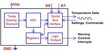
Today’s dense computing and portable electronic devices require sophisticated thermal management, and semiconductor temperature sensors provide this level of sophistication. These ICs combine a temperature sensor with additional functional circuitry and are frequently installed on a heat sink, directly under the microprocessor or a graphics chip. Some CPU ICs have a temperature-sensing transistor made on its own die that can be connected to the external remote-diode temperature sensor for monitoring.
An effective computer thermal management system can be built around a logic output temperature sensor with Low, High, and Control outputs. If the CPU temperature reaches the first preset point above the normal operating temperature due to high ambient temperature, exposure to heat, component failure, or blocked ventilation ports, the Low sensor output changes state and sends a signal to the CPU to reduce the clock rate to lower switching losses and heat dissipation.
Should temperature continue to rise and cross the second set point just below the maximum allowable CPU temperature, the sensor’s High and Control logic outputs change state. The Control output turns on the cooling fan and the High output commands the CPU to further reduce the clock rate. Should the temperature remain above the High set point after a certain amount of time, the computer will be powered down to prevent permanent damage. However, the most reliable shutdown mode bypasses the CPU since at this point the software might not be running correctly. Instead, an output from the sensor is wired directly to the shutdown input of the power supply.
An alternative approach uses a serial output temperature sensor where the CPU periodically polls the sensor and reads the actual temperature through a serial port. If the temperature reaches excessive levels, the processor will attempt to reduce the heat. If the temperature exceeds the absolute maximum limit, the sensor’s comparator output will directly shut down the power supply.
Things to watch
IC temperature sensors are not free from self-heating. Some devices have relatively high operating current, the main cause of self-heating, and this might become an accuracy concern when measuring the temperature of still air, for example. The thermal transfer between the sensor plastic housing and still air is not very efficient, so self-heating can cause the sensor-body temperature to rise above the temperature of the air. Since that sensor actually measures the temperature of its own body, the readings will be higher and thus reduce the accuracy.
Heat radiated or conducted through the printed circuit board by other components near the sensor can also affect the measurement accuracy, so when finding the best position for the sensor, the whole system needs to be carefully reviewed.
For more information go to:
Analog Devices, Inc.
http://www.analog.com
Maxim Integrated Products
http://www.maxim-ic.com
Microchip Technology, Inc.
http://www.microchip.com
National Semiconductor Corp.
http://www.national.com
Texas Instruments, Inc.
http://www.ti.com

Can I use this sensor for monitoring IGBT heatsink temperature where the power draws 100A.
Anjali: Yes, you certainly can. I recommend that you search the reference Web sites I have listed at the end of the articles to find a package type that would best suit the sensor mounting requirements. I don’t know how much space you have available, or how closely you can mount the sensor to the IGBT itself. Look up the specs for the particular IGBT you are using and select a temperature sensor that operates well within the temperature range of the IGBT. Also, make certain that you electrically insulate the sensor from any voltage that the heat sink may be residing above ground. Lastly, shield the lead wires against electrostatic and electomagnetic interference, since the IGBT is likely aperating with ac voltage or producing switching transients. E-mail me if you need more information. jgyorki@designworldonline.com, John R. Gyorki Editorial Director, Design World Magazine.
in the sensing element text there is inforamtion about shorted base and colector and siutable equation, below the second picture there is information about shorted base and emiter, my question: is the equation changed for that case and how? ps. sorry for my english
The equation is correct for an NPN transistor with shorted base-collector.
It seems, that connections of p-n-p transistor as a temperature sensing element at Fig. 2 b) c) are shown wrong way. That is because of transistor is not in conductive condition and it should not be connected to biasing current source. Correct connection is to short base-collector junction as it is mentioned in text above Fig.2
Can U tell me for temperature measurement, is output in terms of frequency better than voltage ? how does it benefits the measurement considering we have analog circuitry ?