Microphone polar patterns, sometimes called pickup patterns, define microphone sensitivity in different directions. The different polar patterns are used for controlling sound pickup and isolating the sound source, or sources, of primary interest from surrounding sources. There are six common microphone polar patterns: cardioid, supercardioid, hypercardioid, omnidirectional, lobar, and bidirectional.
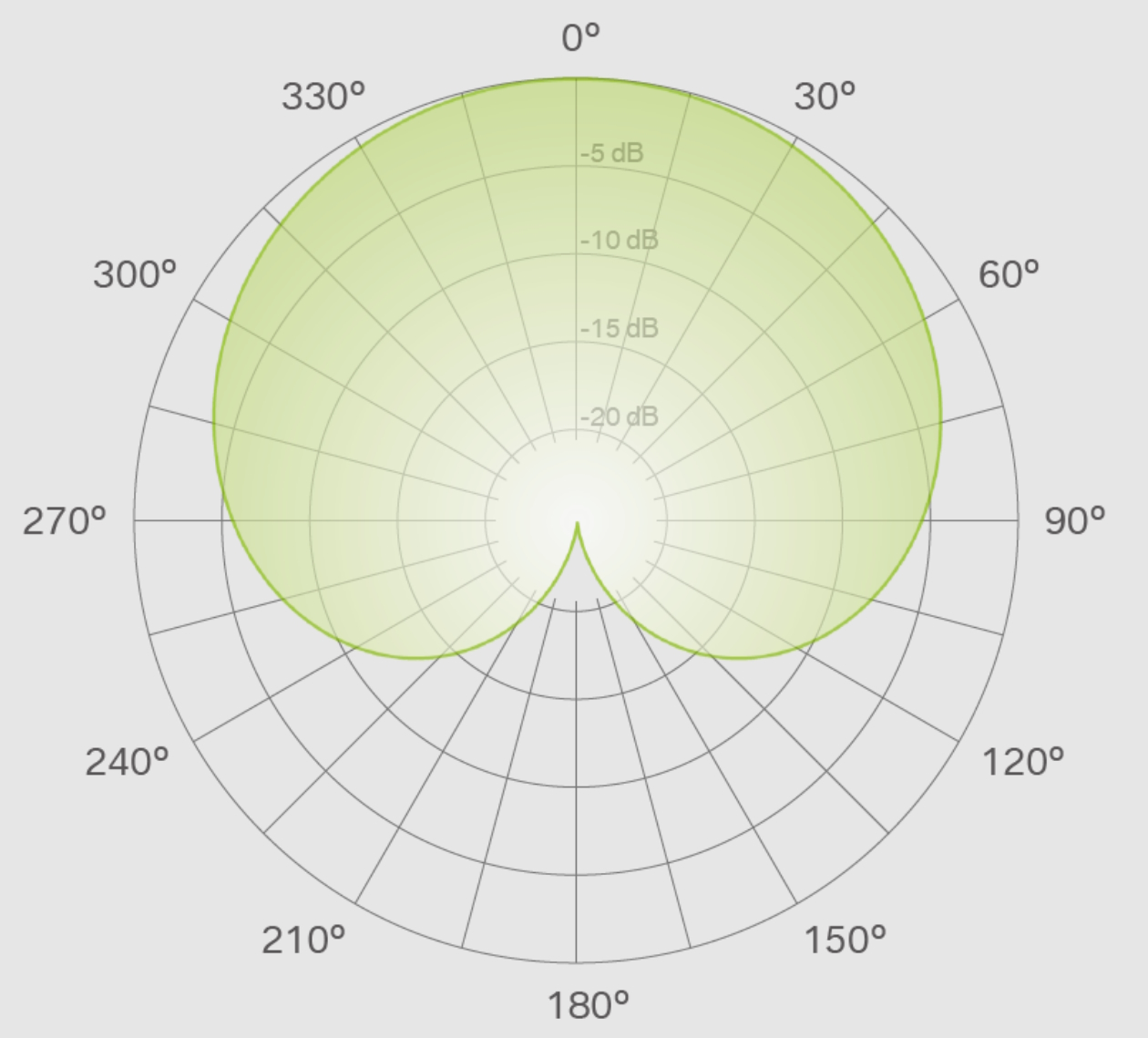
Polar patterns are represented by graphs that show the relative sensitivity of the pickup in a 360° field surrounding the microphone. The front of the microphone (on-axis) is defined as 0°, and behind the microphone (off-axis) is defined as 180°. The polar pattern consists of a series of concentric circles that define microphone sensitivity in 5 dB decrements (Figure 1).
Characteristics of the six microphone polar patterns include (Figure 2):
Cardioid is the most common polar pattern and picks up sound most efficiently from directly in front of the microphone and excludes sounds from the sides and back. These microphones have an optimal pickup area of about 130°. The cardioid, also called off-axis, is least sensitive at 180°. They can isolate individual sound sources, reducing feedback from surrounding sources, and their directionality supports cleanly picking up sounds in noisy environments.
A subset of cardioid is the subcardioid, also called wide cardioid. It’s a little less directional than a cardioid, rejecting more sound from the sides and with a narrower pickup area in the front. The subcardioid also picks up a small amount of sound from behind with a rear sensitivity up to 10 dB lower than its front sensitivity.
Supercardioid is a more focused variant of the cardioid. It has a focus area in front of 115° compared to 130° for the cardioid. Like the subcardioid, it picks up a small amount of sound from the rear. The supercardioid is least sensitive at 125°. Supercardioid is less subject to feedback than the cardioid and delivers higher directionality for cleanly picking up sounds in noisy environments.
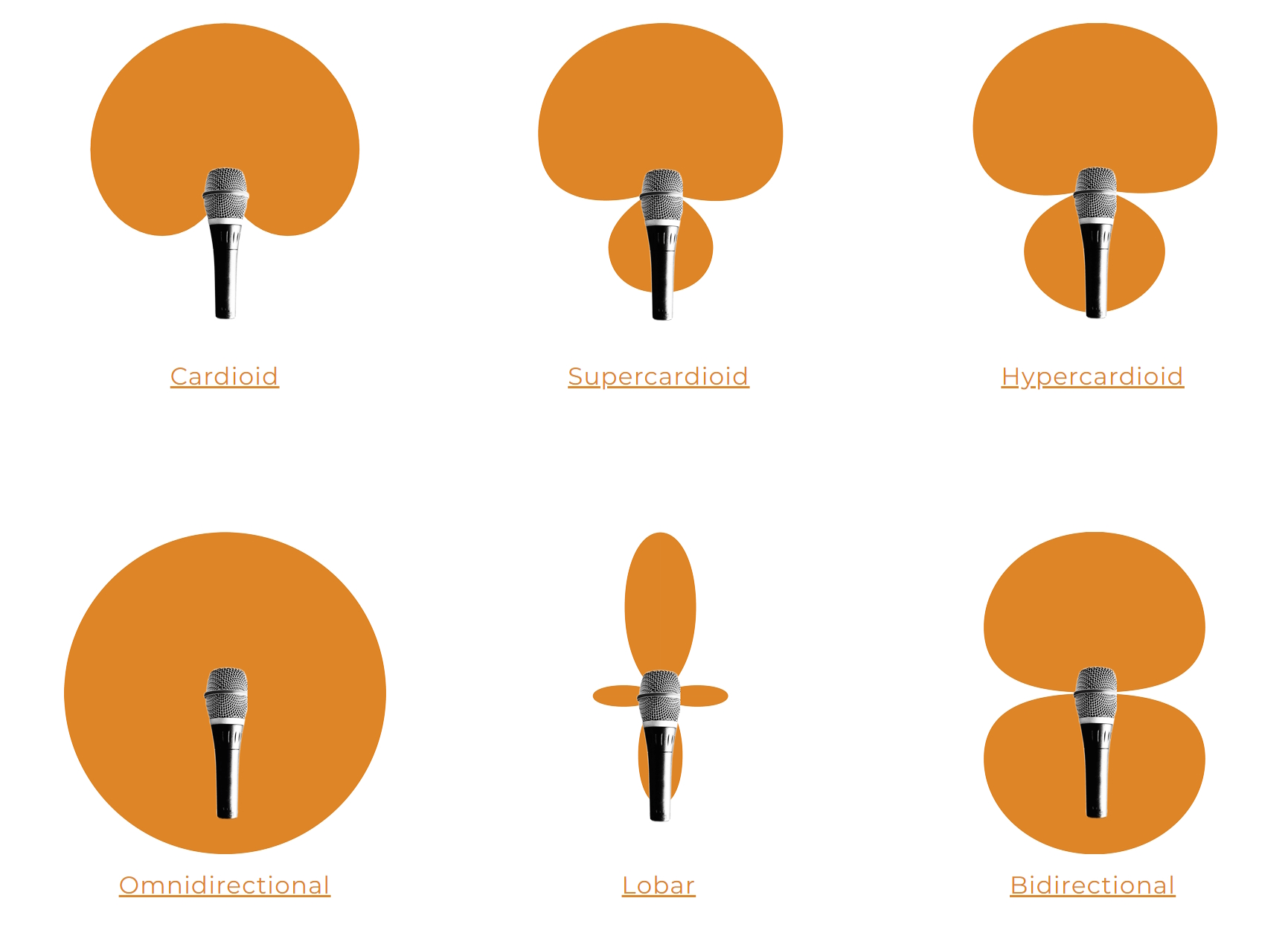
Hypercardioid combines features from the cardioid and bidirectional pickup patterns. It has a focus area in front of 105°. The supercardioid is least sensitive at 110°. While it mostly picks up sound from the front, it also has significant sensitivity to sounds behind the microphone. They tend to be good at rejecting feedback.
Omnidirectional microphones pick up sounds equally well from all directions. It’s the least sensitive to feedback. However, some designs suffer from frequency-related non-linearities and pick up high frequencies with more directivity, leading to higher side rejection of those frequencies, resulting in high-frequency characteristics like a bidirectional microphone.
Lobar, also called a shotgun pattern, is highly directional and can pinpoint the location of sound sources. It has maximum sensitivity at 0°. The lobar pattern has three additional directions of sensitivity, one on each side, at 90° and 270°, and the third at 180°, off-axis. These lobes are less sensitive but nearly as narrow and directional as the main on-axis lobed. In practical lobar microphone designs, the side lobes are tiny, and the microphone works as a variation on a bidirectional polar pattern.
Bidirectional, sometimes called a figure-of-eight pattern, captures sound equally from the front and rear. The pickup angle is typically 90° or less, on the axis at 0° and off-axis at 180°.

Multi-pattern microphones
While microphones are available for each polar pattern described above, some microphones can implement multiple user-selectable polar patterns. The most common design of multi-pattern microphones includes two or more diaphragms to capture the sound waves and/or two or more capsules to convert the sound waves into electrical signals. The most common polar pattern combinations are cardioid, omnidirectional, and bidirectional (Figure 3).
Summary
Microphone polar patterns are optimized for picking up sound from specific directions, minimizing the pickup of sounds from other directions, and controlling feedback. The polar patterns are described as a series of concentric circles that define microphone sensitivity in 5 dB decrements. Microphones are available designed for specific polar patterns that support multiple polar patterns under user control.
References
Large Diaphragm Multi-Pattern Condenser Microphone, Shure
Microphone polar patterns, Lewitt
Microphone Polar Patterns Explained, Perfect Circuit
The 4 Different Types of Microphones for your Studio, SoundRef