Electric vehicle (EV) connectors, contactors, and charging interfaces operate under continuous electrical stress, mechanical loading, and elevated temperatures. With battery voltages approaching 800 V and charging power exceeding 350 kW, early detection of abnormal conditions is a primary design requirement.
This article outlines how EV manufacturers integrate temperature monitoring, current sensing, and fault detection into connector and contactor systems to prevent overheating and enable safe high-power charging and power distribution. It also explains how proximity and pilot signaling in charging interfaces provide coordinated, multi-layer protection across the full charge event.
Temperature sensing in connectors and charging interfaces
As shown in Figure 1, high-voltage (HV) connectors integrate temperature sensors at or near contact interfaces and cable terminations, where I²R losses and contact degradation create localized hot spots.
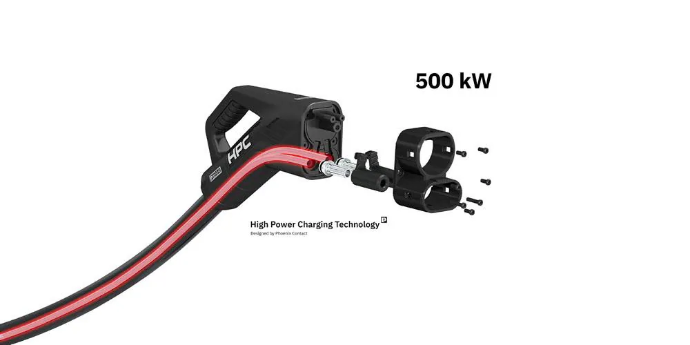
Negative temperature coefficient (NTC) thermistors packaged in high-dielectric ceramic sleeves are placed close to HV contacts. They withstand several kilovolts of isolation and operate continuously up to ~150°C, with short-term capability to 180°C–200°C.
In vehicle HV connectors, these sensors monitor battery-to-inverter and battery-to-contactor interfaces, where thermal feedback triggers current derating or contactor opening when temperature rises rapidly or exceeds defined thresholds.
In DC fast charging interfaces, similar sensing integrates with control protocols. IEC 61851 implementations define over-temperature thresholds: at ≥120°C, the system must shut down immediately, while sustained operation above ~90°C forces derating or shutdown.
Some connector designs monitor resistance or embedded sensing elements in the plug to estimate connector-head temperature in real time, allowing the electric vehicle supply equipment (EVSE) or onboard charger to reduce current progressively rather than waiting for a hard fault.
In high-EMI or very high-voltage environments such as ultra-fast charging systems and high-power busbars, fiber-optic temperature sensing provides an alternative to NTC probes. These sensors are immune to electromagnetic interference (EMI) and inherently isolated, supporting their use in validation setups and high-power charging equipment where electrical isolation is critical.
Current sensing and integrated contactor protection
High-voltage contactors previously relied on external shunt resistors or separate Hall-effect sensors to measure line current. Integrated current-sensing contactors combine the switching element and current measurement within a single device, reducing component count and tightening coupling between measured current and the actuator that interrupts it.
Some designs measure bidirectional line current across a wide DC range, up to several hundred amperes at voltages approaching 600 VDC. They may also include a programmable current-trip function that allows the contactor to open autonomously on overcurrent or short-circuit conditions without external controller intervention. Dual-coil economizer circuits with integrated coil suppression also maintain electromagnetic compatibility (EMC) within the HV compartment.
In charger power stages, current sensing extends beyond switching protection to support control-loop operation. Current transformers (CTs) provide passive, isolated measurement on AC line stages and allow cost-effective overcurrent detection at power-line frequencies.
Hall-effect sensors, particularly closed-loop compensated designs, extend measurement to DC buses and high-frequency power stages where CT bandwidth and DC response limitations constrain performance. The two technologies operate in complementary roles within the same charger architecture.
In parallel, residual current monitoring provides a standards-critical protection layer. In EV charging systems, a smooth DC residual current of approximately 6 mA can saturate conventional toroidal sensing cores used in Type A residual current device (RCD) architectures, degrading or eliminating their ability to detect superimposed AC leakage.
IEC 62955 mandates DC-capable residual current detection, driving designs toward Type B RCDs or residual current differential device (RDC-DD) implementations, as shown in Figure 2, often using fluxgate sensors.
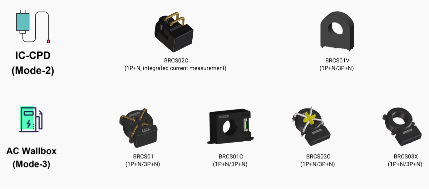
These devices detect both AC and DC leakage with low drift over temperature and support compliance-grade detection in EVSE designs.
Fault detection and contactor weld monitoring
Beyond overcurrent protection, EV power distribution systems implement diagnostic sequences to detect mechanical faults in contactors, including welded or stuck contacts that prevent safe shutdown. These diagnostics rely on coordinated current, voltage, and position sensing interpreted by battery management system (BMS) or vehicle control unit (VCU) firmware.
One approach uses voltage-based weld detection, which applies controlled switching sequences during a diagnostic interval to infer contact state. Control logic opens one contactor, closes another, and measures the resulting voltage between nodes. If the voltage does not respond as expected, a welded contact is indicated, and further HV operation is inhibited.
Auxiliary contacts, mechanically linked to the main contacts and monitored independently, provide a complementary signal: a mismatch between the coil command state and auxiliary contact feedback indicates a weld or jam condition and triggers safe-state sequencing.
DC fast charging standards define maximum reaction times for overcurrent, short-circuit, overvoltage between DC rails, and loss of protective earth, which these diagnostic requirements must meet.
As a result, fault detection circuitry and algorithms must operate within millisecond response windows. These constraints reinforce integrated sensing architectures, where current measurement and protection logic reside close to or within the contactor rather than depending on multi-node communication latency.
Proximity, pilot, and charging interface sensing
AC and DC charging interfaces integrate dedicated sensing channels that verify connection state, cable rating, and fault conditions before enabling power and during charging.
As shown in Figure 3, the Proximity Pilot (PP) line in IEC 62196 Type 2 connectors encodes the cable conductor cross-section as a resistor value within the plug, which the EVSE measures to limit output current and prevent cable overload without requiring active communication from the vehicle.
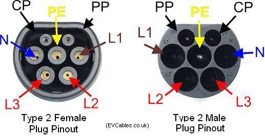
The Control Pilot (CP) line operates in parallel, using voltage level and pulse-width modulation (PWM) duty cycle to communicate EV connection state, vehicle readiness, fault conditions, and the maximum current the vehicle may draw from the EVSE. The vehicle must follow the specified current limit, while CP state transitions are monitored continuously for faults.
Loss of proximity, CP state anomalies, overtemperature at the connector, overvoltage between DC rails, and loss of protective earth each have defined detection and reaction times that the EVSE must meet for compliance.
Together, these channels form a multi-layer interlock that maintains continuous verification of mechanical connection, cable rating, vehicle readiness, and thermal status during the charging session. A fault in any channel reduces current or terminates the session before damage to the connector, cable, or vehicle occurs.
Summary
Sensing technologies embedded in EV connectors, contactors, and charging interfaces enable coordinated protection across the HV power distribution chain. Thermal monitoring drives derating and shutdown, integrated current sensing enables fast fault response and weld detection, and DC-capable residual current monitoring addresses leakage that AC-only architectures cannot detect. Together with proximity and pilot signaling, these systems maintain continuous visibility into connection state, operating conditions, and fault behavior.
References
High-Voltage Temperature Sensors for Connectors in e-Mobility; TDK App Note, European Passive Components Institute
EV/EVSE Testing and Certification, OpenChargeAlliance
IEC 61851: Everything You Need to Know About the EV Charging Standard, eInfoChips
Proximity Pilot, IQLaaD
Relays & Contactors for EV Charging Applications, DuraKool
EV Battery Temperature Sensors, Amphenol
Reliable Temperature Monitoring During the Charging Process for xEV Batteries, TDK Electronics
Supporting EV Growth with Precision Sensors, SenScience
Thermal Management for BEVs with TDK Sensor Solutions Optimized by Computer-Aided Modeling, TTI
Related EEWorld content
Why Pressure Sensing is Critical to EV Thermal Management
How 800 V+ Architectures Impact EV Connector and Contactor Requirements
How Adhesives and Sealants Impact EV Connector Reliability and Service Life
Q&A: How Sensing Advances are Shaping the Future of EV Battery Safety
What Engineering Requirements Shape EV High-Voltage Connectors and Contactors?






Leave a Reply
You must be logged in to post a comment.