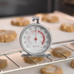
Temperature is a widely measured real-world physical variable, but achieving credible results is harder than it seems, even for a simple device such as a kitchen oven.
Calibration of a sensor and its associated electronics channel before making critical measurements or monitoring system performance is a common requirement in many situations. In some cases, it’s important to know the sensor accuracy to a relatively tight specification, such as better than one or even one-tenth degree Celsius (C); in other cases, a much looser standard of plus or minus several degrees C is all that is needed, and there are even cases where reading this is “only” accurate to ten or more degrees is acceptable. The calibration challenge consists of two distinct parts: the sensor by itself, the other being the electronics and readout independent of the sensor.
Calibrating the electronics alone is relatively easy. You can use an electronic unit that generates a known and adjustable electrical signal (such as voltage, current, or frequency) that looks like the one the sensor would generate. For example, the Omega Engineering CL540ZA Thermocouple Simulator can simulate the output of 14 different thermocouple types (Figure 1).
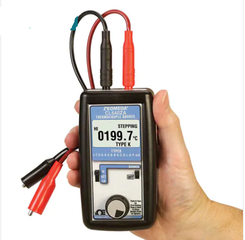
It’s simple to use: you just connect it in place of the actual thermocouple, select the thermocouple type you wish to simulate, and then set the dial to the “temperature” a real thermocouple would be sensing. The unit then generates a voltage that is the same as a real thermocouple would create at the designated temperature. It automatically corrects for the well-known, standard non-linearities of the Seebeck effect associated with each thermocouple type. The accuracy of such a simulator is on the order of between 0.1 to 0.5⁰C, depending on range and thermocouple type.
Calibrating the sensor
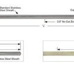
In contrast to the calibration of the sensor channel, calibration of a temperature sensor such as a thermocouple itself is difficult. First, unlike length, mass, or force, “temperature” is somewhat intangible. It is difficult to create and validate that a material or chamber is at the desired temperature (think of how proving rings greatly simplifies mass and force-sensor calibration). Second, there’s the issue of where the calibration is being implemented, in order of difficulty:
- for a sensor at the bench or a test setup, which seems easy (but isn’t).
- in the actual system where it is being used, but with the system not in actual use.
- in the system while the system is being used (think of an aircraft in flight).
Even the first and easiest situation is a calibration challenge. In theory, you can calibrate the sensor by using a “box,” which creates a known temperature environment chamber and then inserting the sensor under evaluation in that chamber. Alternatively, you can calibrate your sensor by comparing its output to a known, better one (which you need to have available) in a temperature-controlled chamber.
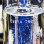
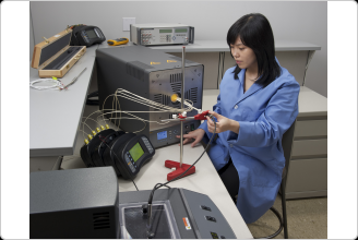
For example, the Fluke Calibration 9118A Thermocouple Calibration Furnace is a horizontal, open-ended tube furnace with a temperature range of 300º C to 1200º C (Figure 2). It is used for calibration by comparison of the thermocouple under evaluation against a secondary-standard thermocouple. It contains an internal isothermal block for the highest accuracy to ensure that the reference thermocouple and the one under test are as close to each other thermally as possible.
The next part of this article reviews some temperature basics.
EE World Online Related Content
What are cryogenic temperature measurements? Part 1
What are cryogenic temperature measurements? Part 2
Solid-state temperature sensing Part 1 — principles
Solid-state temperature sensing, Part 2 – application
The proving ring – An alternative to dead-weight calibration, Part 1
The proving ring – An alternative to dead-weight calibration, Part 2
References
Fluke, “How to Calibrate a Thermocouple
Fluke, “9118A Thermocouple Calibration Furnace
Omega Engineering, “Common Techniques to Calibrate Thermocouples
Electronic Design, “IR Thermometer Reads to 0.001°C with Accuracy, Stability
NIST, “Kelvin: Introduction
NIST, “SI Units – Temperature
NIST, “The Calibration of Thermocouples and Thermocouple Materials
IEEE Spectrum, “Nathan Myhrvold’s Recipe for a Better Oven
Ampleon, “RF Solid State Cooking White Paper”