The interface electronics for the LVDT must excite the primary-side winding with a sine wave and then demodulate the two resultant secondary-side waveforms; modern ICs make this analog-signal process fairly straightforward.
The first two parts of this LVDT article (see References) looked at the LVDT transducer itself, along with its attributes and history. This second section looks at the equally important topic of the LVDT interface electronics, which makes this simple, accurate, and reliable transducer into a viable, practical, and widely used linear-position indicator.
Q: Does the LVDT require excitation?
A: Yes. Unlike thermocouples or piezo-based sensors, which generate a voltage, the LVDT is an entirely passive transducer consisting of wound coils. As with any transformer, it needs primary-winding AC excitation to generate its response.
Q: What does this excitation signal look like?
A: It is almost always a low-distortion, constant-amplitude sine wave typically between 1 kHz and 20 kHz. The amplitude is usually between 1 and 24 Vrms, and the required current is between 20 and 100 mA, depending on the LVDT specifics. The classic Wein-bridge oscillator architecture is often used due to its simplicity and low distortion. Higher voltage improves SNR and resolution but requires more power and induce more dissipation – a common tradeoff. The AC signal is also used to create a corresponding square wave for the timing of synchronous demodulation.
Q: What is the basic input/output relationship?
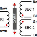
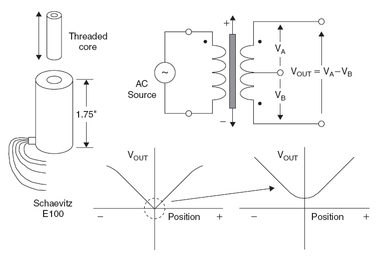
The secondary windings are wound out of phase with each other. When the core is centered, the voltages in the two secondary windings oppose each other, and the net output voltage is zero. As the core moves from its center “neutral” position, the voltage in the secondary winding toward which the core is moved increases, while the voltage of the other winding decreases. The result is a differential voltage output that is linear with the core’s position shift.
Q: What are some related issues?
A: There are inevitable slight mismatches between the two secondary windings as well as leakage inductance. The perfect “true null” does not occur when the core is centered because of winding asymmetry. These errors are relatively small, and many users can ignore them, but they can be trimmed or calibrated out to a large extent.
Q: How is the output signal made useful?
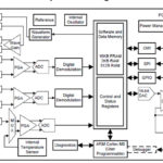
A: Synchronous demodulation – a long-established demodulation approach – is used, Figure 1. This involves having the secondary-side output be demodulated with a relationship to the phase of primary-side excitation.
Q: How is the demodulation accomplished?
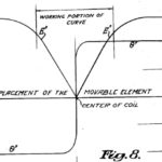
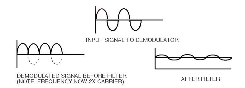
A: The function of the demodulator is to take the AC output of the transducer and convert it into a useful dc voltage proportional to displacement, Figure 2. In a basic signal-conditioning circuit, the absolute values of the two output voltages of the secondary outputs are subtracted. Using this technique, both positive and negative variations about the center position can be measured.

Q: What do the waveforms look like and what filtering is needed?
A: The output is fed through a low-pass filter, which removes the majority of the AC components leaving a steady DC voltage, Figure 3. This filter often also includes circuitry for setting coarse zero, fine zero, and fine gain, and also has connections so that the filter characteristics can be altered.
Q: What are some error sources?
A: When measuring absolute voltage values, there will always be errors due to offsets, drifts, and measurement inaccuracies. For this reason, nearly all LVDT circuitry uses a ratiometric design, a common and long-practiced technique for eliminating absolute errors by using ratios between values, which in theory track and so can cancel errors to a large extent. The Wheatstone bridge is the classic radiometric approach.
Q: What parts of the LVDT interface circuit benefit from ratiometric circuitry?
A: Three locations can make use of this well-known approach (Figure 4):
- Between primary waveform generator and secondary signal conditioner;
- Between the two secondary coil outputs;
- In the power supply and signal output sections.
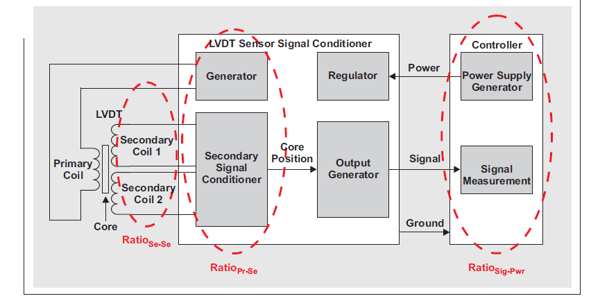
Ratiometric approaches are used to eliminate changes due to from the excitation voltage shifts when measuring LVDT signals, and also compensate for and eliminate drift and other variances of the LVDT. While such an approach is somewhat more complicated than a non-ratiometric design, the benefits are significant, while the difference between their circuitry is now almost trivial with modern ICs (this was not the case in the pre-IC and pre-transistor tube-based eras of long ago).
The second and final part of this FAQ will look at some standard LVDT interface ICs and implementations.
EE World References
LVDT position sensor, Part 1: Basics and principles
LVDT position sensor, Part 2: Characteristics
The proving ring – An alternative to dead-weight calibration, Part 2
Miniature LVDT Position Sensors Operate In Applications With Harsh, High-Pressure Environments
Miniature LVDT sensors provide accurate position/path measurements in tight spaces
Radiation Resistant LVDT Linear Position Sensor Designed For Nuclear Power Generation Plants
LVDT position sensors provide feedback in robotic applications
High-Pressure And Seawater-Resistant Position Sensors
Extreme High-Temperature Position Sensors
External References
Sensor Wiki, “Linear Variable Differential Transformer (LVDT)”
Wikipedia, “Linear variable differential transformer”
TE Connectivity, “LVDT Tutorial”
Omega Engineering, “What is a LVDT?”
H.G. Schaevitz LLC/Alliance Sensors Group, “LVDT Position Sensor Products”
Analog Devices, “Linear Variable Differential Transformers”
Analog Devices, “Two New LVDT Interface ICs Offer Choice of Analog or Digital Output”
Analog Devices, ”Precision LVDT Signal Conditioning Using Direct RMS to DC Conversion”
Analog Devices, “Low Power LVDT Signal Conditioner with Synchronous Demodulation”
Analog Devices, “AD698 Universal LVDT Signal Conditioner”
Analog Devices, “CN0288 LVDT Signal Conditioning Circuit”
Texas Instruments, “Ratiometric measurements in the context of LVDT-sensor signal conditioning”
Texas Instruments, “PGA970 Use Case for LVDT Applications“
Texas Instruments, “PGA970 LVDT Sensor Signal Conditioner”