The linear variable differential transformer (LVDT) is a widely used, inherently rugged, linear-position sensor offering accurate and consistent performance over a wide span of distances.
Sensing of physical position is among the most commonly needed parameters in industrial, military/aerospace, robotics, scientific measurement, and control applications, and there are many sensors in use to accomplish this. Further, if you can determine the position in real-time, you can also use analog circuitry or digital calculation to determine velocity and acceleration by differentiating the position data once or twice, respectively, with respect to time. The selection of the most suitable position-sensing transducer is a function of accuracy, distance, ruggedness, cost, physical access and placement, contact or non-contact, and many other factors, with no single type of transducer being the “best” one.
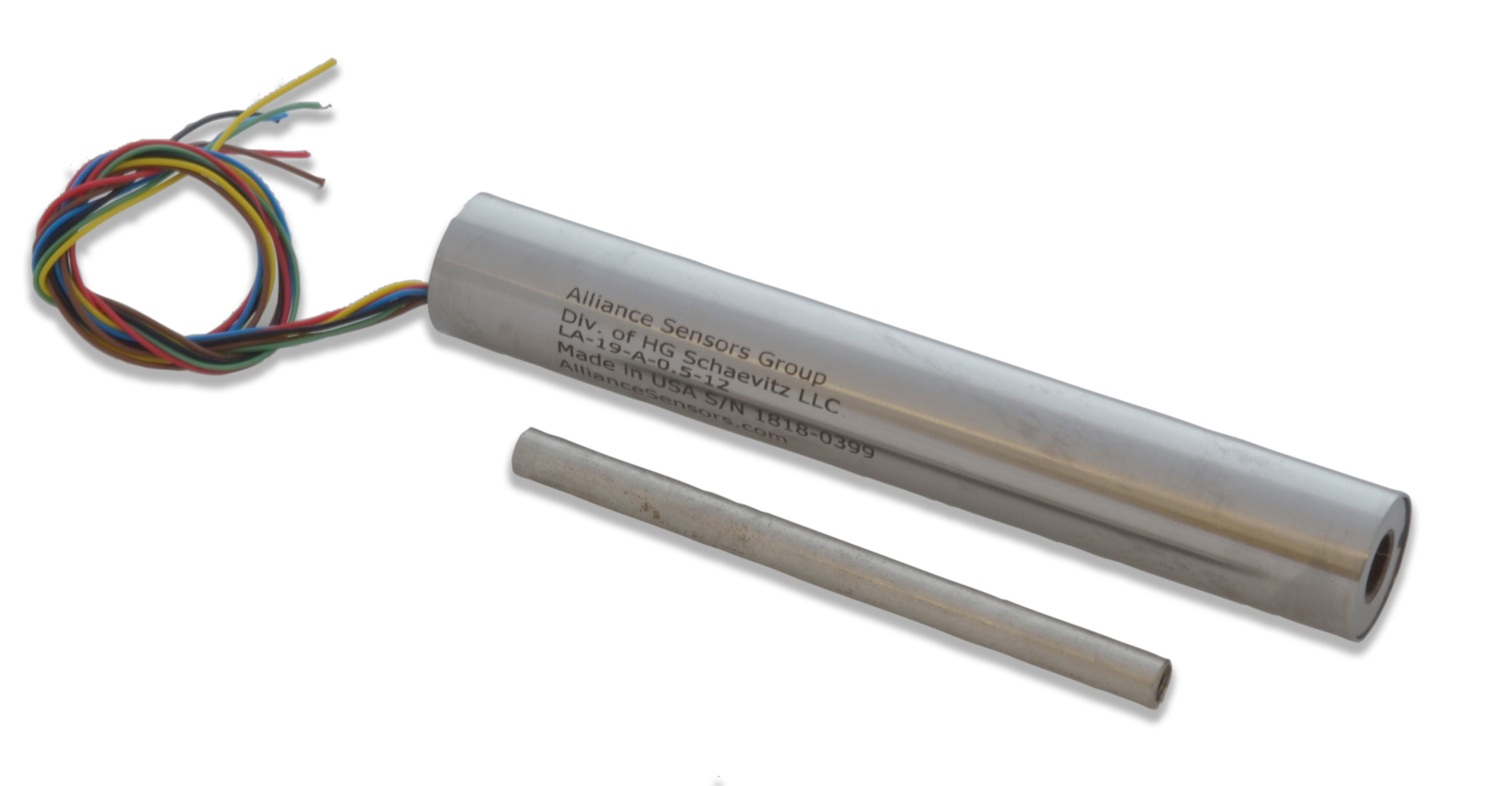
One of the most widely used position transducers is the linear variable displacement transducer or LVDT (Figure 1). This two-part article will look at the LVDT principle, operation, and attributes; a subsequent article will look in detail at its electronic interface.
Note that for the LVDT, the adjective “linear” refers to the transducer’s measurement path, not its readout linearity (which s quite good). It has a close sibling which is formed as a rotary-angle sensor, and so is called the rotary variable displacement transducer (RVDT). Despite the difference in physical appearance, almost all aspects of the physical unit and electrical interface are identical. Therefore, we will refer to the LVDT while recognizing that most of the specifics apply identically to the RVDT as well.
Q: What is an LVDT?
A: The LVDT is a position transducer which uses a trio of transformer-like windings and magnetic coupling to provide a highly accurate, absolute readout of linear position. The basic LVDT is a model of simplicity of concept.
Q: How so?
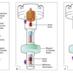
A: The internal structure consists of a primary winding centered between a pair of identically wound secondary windings, symmetrically spaced on either side of the primary coil (Figure 2). This entire multiple-winding assembly is considered as the stationary element of the position sensor. Mechanically, the coils are wound on a one-piece hollow form, often on a thermally stable glass-reinforced polymer, encapsulated against moisture, wrapped in a high permeability magnetic shield, and then sealed in an aluminum or stainless steel cylindrical housing.
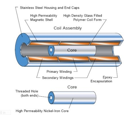
The moving part of the LVDT is its core, which is a basic rod or tube of magnetically permeable material. The core is usually threaded at one or both ends for convenience for mechanical connection to the object whose position is being measured and moves freely through the coil’s hollow bore. This bore of the LVDT body has a large-enough diameter so that the fit between the hole and the core is not tight; instead, there is substantial clearance between the coil bore and core, and thus there is no physical contact between the two.
Q: How is the LVDT operating principle?
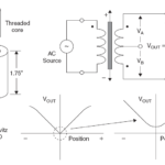
The LVDT is a transformer with one primary coil and two secondary coils, and the relative output between the two secondary coils is a function of the core’s position. The LVDT’s electrical output signal is determined by the relative differential AC voltage between the two secondary windings, which varies with the linear position of the core within the LVDT coil (Figure 3 center).
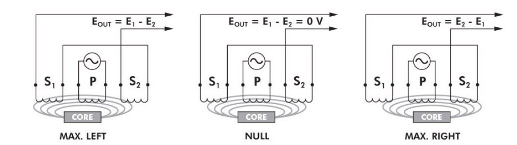
The LVDT’s primary winding, P, is energized by a constant-amplitude AC sine-wave source, which is usually between 1 kHz and 10 kHz. The magnetic flux, which is developed, is coupled by the core to the adjacent secondary windings S1 and S2. In the center position, with the core located exactly midway between S1 and S2, equal flux is coupled to each secondary winding. Thus the voltages E1 and E2 induced in windings S1 and S2, respectively, are equal. At this reference midway core position, known as the null point, the differential voltage output (E1 – E2) is nominally zero.
If the core is moved closer to S1 than to S2 (Figure 3 left), more magnetic-field flux is coupled to S1 and less to S2, so the induced voltage E1 increases while E2 decreases, resulting in the differential voltage (E1 – E2). Conversely, if the core is moved closer to S2 (Figure 3 right), more flux is coupled to S2 and less to S1, so E2 increases as E2 decreases, resulting in the differential voltage (E2 – E1).
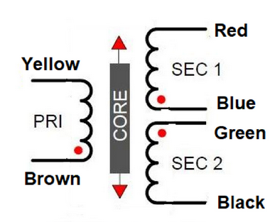
As the two secondary coils are in series, the LVDT has four lead wires, although many LVDTs bring out the secondary lead pairs separately for convenience and test, in which case there are six distinct leads (Figure 4).
Q: What does the LVDT output look like?
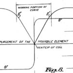
A: The basic output of the LVDT is a sine wave with amplitude proportional to off-center position, and phase (0⁰ or 180⁰) depending on which side of center the core is located. The signal must be demodulated via full-wave rectification. The maximum value of EOUT occurs at maximum core displacement from null (center) position and is a function of the amplitude of the primary-side excitation voltage and the sensitivity factor of the particular LVDT; typically, it is fairly substantial at several volts (RMS). The demodulated output is a DC signal with an amplitude, which is linear versus position (displacement) of the core – no correction for nonlinearities is needed, unlike, for example, what is needed to correct the output of a thermocouple or RTD temperature sensor.
Part 2 of this FAQ looks at some of the attributes of the LVDT, which make it an attractive position sensor.
EE World References
The proving ring – An alternative to dead-weight calibration, Part 2
Miniature LVDT Position Sensors Operate In Applications With Harsh, High-Pressure Environments
Miniature LVDT sensors provide accurate position/path measurements in tight spaces
Radiation Resistant LVDT Linear Position Sensor Designed For Nuclear Power Generation Plants
LVDT position sensors provide feedback in robotic applications
High-Pressure And Seawater-Resistant Position Sensors
Extreme High-Temperature Position Sensors
External References
S. Patent 2,196,809, “Telemetric System”
Sensor Wiki, “Linear Variable Differential Transformer (LVDT)”
Wikipedia, “Linear variable differential transformer”
TE Connectivity, “LVDT Tutorial”
Omega Engineering, “What is a LVDT?”
H.G. Schaevitz LLC/Alliance Sensors Group, “LVDT Position Sensor Products”
Analog Devices, “Linear Variable Differential Transformers”
Analog Devices, “Two New LVDT Interface ICs Offer Choice of Analog or Digital Output”
Analog Devices, ”Precision LVDT Signal Conditioning Using Direct RMS to DC Conversion”
Analog Devices, “Low Power LVDT Signal Conditioner with Synchronous Demodulation”
Texas Instruments, “Ratiometric measurements in the context of LVDT-sensor signal conditioning”
Texas Instruments, “PGA970 Use Case for LVDT Applications“