The difference is measurement accuracy. Using 2-wire resistance temperature detector (RTD) sensing provides good accuracy (maybe), the accuracy of 3-wire sensing is better, and 4-wire sensing provides the best accuracy. In addition, there’s the option of using Wheatstone bridge topologies to improve the performance of 2- and 3-wire RDTs.
This FAQ begins with a review of the basics of RDT devices, looks at the tradeoffs between 2-, 3-, and 4-wire sensing, and closes with a brief look at Wheatstone bridges and temperature sensing.
Designers can choose from thermistors and thermocouples in addition to RTDs. In many applications, RTDs are especially good choices due to their fast response times, repeatability, and superior sensitivities up to a few hundred µV/°C. And RTDs can be used over a wide range of –200°C to +800°C with a nearly linear behavior.
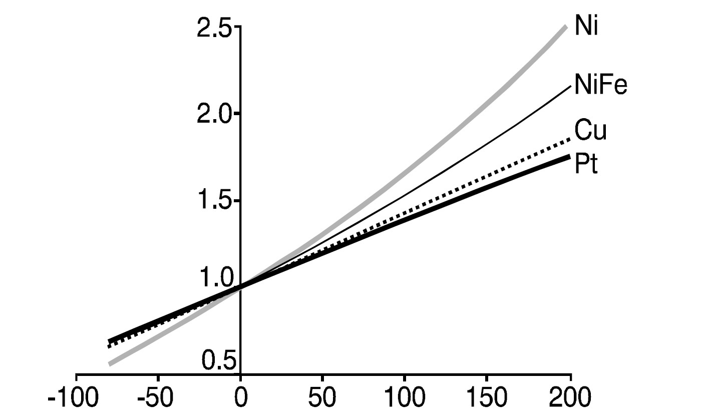
RTDs are available using various materials such as nickel, copper, and platinum. While platinum RTDs (PRTDs) can be more costly, other metals are not as widely used since they are not as stable or repeatable as PRTDs (Figure 1). In addition, PRTDs are not affected by corrosion or oxidation. When accuracy and repeatability are important over temperatures from -200 to +800 °C in industrial, medical, and aerospace applications, PRTDs are the best choice.
The development of modern PRTD standards, such as IEC 60751 and ASTM 1137, allows substantial interchangeability of sensors between systems based on the specified tolerances and temperature coefficients. These standards make it easy to replace a sensor with one from the same or a different manufacturer while ensuring rated performance with minimal redesign or recalibration of the system. However, designers need to be aware that IEC 60751 was revised by the IEC in 2008 and again in 2022. IEC 60751:2022 introduced several significant technical changes. A review of those changes is beyond the scope of this FAQ.
The three most-common PRTDs are the PT100, PT500, and PT1000, which have resistances of 100Ω, 500Ω, and 1000Ω, respectively, at 0 °C. PT1000 is currently the most commonly used PRTD type. RTDs are available for use in 2-, 3- and 4-wire configurations (Figure 2).

The 2-wire RTD configuration in the simplest implementation and the two wires that supply the RTD with excitation current (I) to measure the sensor voltage (and therefore the temperature). Because the resistance calculated for the circuit includes the resistance in the lead wires and connectors as well as the resistance in the RTD element, the result will always contain some degree of error. Due to low sensor resistance, even relatively low wire resistances (RL) can result in significant measurement inaccuracies.
Using the shortest possible lead lengths and connectors with low contact resistances can reduce this error, but it’s impossible to eliminate it. A larger gauge wire with less resistance also helps minimize the error. In cost-sensitive applications that don’t require high accuracy, a 2-wire RTD configuration can be a viable option.
3 wires are better
The most common RTD configuration in industrial systems uses three wires to provide a good balance between cost and accuracy. Two wires connect the sensing element to the monitoring device on one side of the RTD, and one links to the other side of the RTD. If three identical type wires are used, and their lengths are equal, then RL1 = RL2 = RL3. Referring to Figure 1 above, a total system resistance is measured by measuring the resistance through leads 2, 3, and the resistance element (RL2 + RL3 + RTD). The resistance of just the lead wires can be measured through leads 2 and 3 (RL1 + RL2). Since all lead wire resistances are equal, subtracting this value (RL1 + RL2) from the total system resistance (RL2 + RL3 + RTD) leaves RTD, and an accurate temperature measurement can be made.
There are a couple of concerns with this approach:
- The measurement will be accurate only if all three connecting wires have the same resistance.
- In a practical design, measuring the various lead resistances can be challenging.
If these concerns are not addressed, the basic 3-wire configuration is not necessarily an accurate way to measure temperature using an RTD. The 4-wire approach overcomes these challenges.
4 wires are best
In a 4-wire RTD configuration, two wires link the RTD to the monitoring device (RL2 and RL3, in Figure 1), and two other wires (RL1 and RL4) deliver the current used for measurement. Separating the excitation current wires from the measurement wires eliminates the sources of error found in 2-wire and 3-wire configurations. This configuration produces the most accurate measurements, but it’s the most complex, time-consuming, and expensive to implement.
Bridges to improved 2- and 3-wire measurements
Wheatstone bridge configurations can be used to obtain improved accuracy when using 2- and 3-wire RTD devices. To detect the small variations of resistance in an RTD in a 2-wire configuration, a temperature transmitter in the form of a Wheatstone bridge can be used (Figure 3A). The circuit compares the RTD value with three known and highly accurate resistors. In this circuit, when the current flow through the measuring device (Vout) is zero, the bridge is said to be in null balance. This is called the zero or set point for the RTD temperature output. As the RTD temperature increases, Vout increases, and the temperature can be measured. If the RTD is installed some distance away from the Wheatstone bridge transmitter, the resistance of the wires changes as the ambient temperature fluctuates, introducing an error into the measurement. To eliminate this problem, a three-wire RTD Wheatstone bridge configuration can be used (Figure 3B).
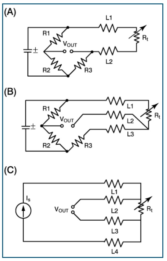
In a 3-wire RTD Wheatstone bridge configuration, the connecting wires (L1, L2, and L3) are the same length and, therefore, the same resistance. The excitation current source is connected to one end of the RTD and the Wheatstone bridge. Since L1 = L2, the resistances of the wires cancel, and the effect of the connecting wires is eliminated.
Summary
PT1000 RTDs are the most commonly used measuring device when accurate and stable temperature measurements are needed. The choice between 2-, 3- and 4-wire thermal sensing involves tradeoffs between increasing cost and complexity versus improved measurement accuracies. In some applications, Wheatstone bridge configurations can improve the accuracy of 2- and 3-wire sensing, but with increased complexities.
References
A Basic Guide to RTD Measurements, Texas Instruments
High-Accuracy Temperature Measurements Call for Platinum Resistance Temperature Detectors (PRTDs) and Precision Delta-Sigma ADCs, Maxim Integrated Products
How to Choose Between a RTD PT100 vs Pt1000?, Omega Engineering
Resistance Thermometry: Principles and Applications of Resistance Thermometers and Thermistors, Minco
RTD Bridge Circuits, The Process Technology and Operator Academy
Simple Realization of a Fully Integrated 4-Wire RTD Temperature Measurement System for High Precision Measurement Applications, Analog Devices


Leave a Reply
You must be logged in to post a comment.