A variety of sensor technologies are being employed to improve the performance of 5G, or mmWave, communications. Sensors can help mmWave systems optimize transmit power to optimize device power consumption and operating range. They can be used to monitor movements within a building environment. Motion sensors such as inertial measurement units (IMUs) can help identify causes of misalignments in antenna directionality that can reduce performance. Sensor fusion is being used to support design and testing of 5G wireless communications devices with high accuracy across a wide range of signal frequencies and scenarios. And in the future, “beyond 5G” (B5G) and 6G systems, the communications system and the sensor system are expected to merge into a joint communications and sensing system.
An antenna module with integrated frequency modulated continuous wave (FMCW) radar sensing can enable customer premises equipment (CPEs) to constantly monitor surrounding environments and adjust transmit power to optimize device power consumption and operating range (Figure 1). The antenna module can support from 16 to 64 dual-polarization antenna elements, with up to 48 dBm of peak EIRP, complying with Power Class 1 and 5 devices, and delivering wide ‘scan angle’ coverage with over 30% improvement compared with previous antenna modules.

RF sensing designs can also use Wi-Fi to monitor activities in a building environment and improve 5G performance. For example, it’s possible to track the position of a moving individual or mobile robot without the need for the person or robot to carry a device. Proof of concept systems have been designed using data from multiple Wi-Fi access points combined with specifically designed ML algorithms. A user walks through the areas to be monitored to establish the baseline environmental information, and a smartphone app creates a basic map of the interior. Wi-Fi sensing produces positional errors under one meter. It’s being developed for a variety of applications such as security, home healthcare, and home automation systems where accuracy of 1 meter is sufficient. For applications such as vehicular systems, sensor fusion can produce higher levels of precision in dynamic and challenging environments.
Sensor fusion improves communication
Location-based beamforming is an important aspect of 5G system performance, and it demands precise information on the location of receivers. IMUs are one way to identify motions causing misalignments in antenna directionality. IMUs such as accelerometers and gyroscopes can detect the cause and extent of errors from translational or rotational movements. When the extent of beam misalignment is understood, the antennas can be reconfigured as needed. In addition, data from IMU sensors can be used to predict the next misalignment and avoid link disruptions, decreasing the number of beam searches and lowering the MAC overhead.
Accelerometers can be used to detect and measure linear, or translational, motion. A combination of accelerometer data and/or gyroscope data can identify and quantify rotational motion. External signal blockages can also result in link interruptions while the device or platform is moving, requiring the use of non-line-of-sight (NLOS) paths. Without sufficient data, it can be difficult to identify the cause of link degradation. Further complicating the problem, the solution to correct the lost link because of one cause of error is not necessarily compatible with corrections for the other errors. That makes it important to understand the source of link interruptions so they can be addressed in an effective and timely manner. Using data from IMU sensors can help to predict movement and aid in the calculation of the correct antenna weight vectors to maintain a stable link.
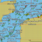
In addition, the large number of antennas usually found in mmWave devices enables the calculation of accurate angle of departure (AOD) and angle of arrival (AOA) estimates. In mmWave systems, combining AOD or AOA with time of arrival (TOA) measurements can make position estimation possible with a single anchor. Position estimations based on a combination of 5G and IMU sensing can produce position estimations that are superior to GNSS/IMU positioning results (Figure 2).

Sensor fusion is often implemented using a Kalman filter to combine the mmWave and IMU measurements. Another benefit is that the Kalman filter and IMU sensor fusion can maintain the positioning during the line-of-sight (LOS) blockages, where no measurements are received from the mmWave side, making the sensor fusion technique robust even in the event of LOS blockages.
5G SAMURAI
Engineers at the National Institute of Standards and Technology (NIST) have developed a flexible, portable system to make synthetic aperture measurements of uncertainty in angle of incidence (SAMURAI) to support design and testing of 5G wireless communications devices with high accuracy across a wide range of signal frequencies and scenarios. According to NIST, this is the first system to offer 5G wireless measurements with accuracy that can be traced to fundamental physical standards. Measurements can take several hours to complete, and a suite of sensors records all aspects of the (stationary) channel for later analysis. The sensors measure environmental factors such as temperature and humidity, drift in accuracy of the measurement system, and location of scattering objects.
The designers named the system SAMURAI because it measures received signals at many points over a virtual synthetic aperture, allowing reconstruction of the incoming energy in three dimensions, including the angles of the signals. The system consists of two antennas to receive and transmit signals, synchronized instrumentation and sensors to generate the transmissions and analyze the reception, and a six-axis robot arm to position the receiver antenna at the various grid points that make up the synthetic aperture. Small metallic object such as cylinders and flat plates are used during the test to simulate the impact of buildings or other objects on signal transmissions.
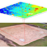
Accurate and repeatable antenna positions are possible using the robot arm and the arm can be programmed to move through a variety of 3D reception patterns. To further improve positional accuracy imaging data from a camera can be integrated into the system to track the antennas and measure the relative positions of objects that scatter the channel signals. SAMURAI is deployed on a 5 by 14 feet (1.5 by 4.3 meters) optical table (Figure 3). The system is designed for a variety of tasks from measuring reflective channels when metallic objects scatter signals to verifying wireless device performance with active antennas.

Joint communications and sensing beyond 5G
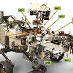
The high bandwidths available in 5G mmWave, and possibly sub-THz 6G bands, will result in the proliferation of small cells that can support next-generation applications beyond 5G (B5G) and 6G deployments such as cellular joint communications and sensing (JCAS) systems, also called RadCom systems. Combining MIMO with AI/ML will enable the development of dual-function JCAS systems. A JCAS system would include beamforming antennas, various pieces of user equipment (UE) for data transmission, and sensing objects or people (Figure 4). The use of mmWave or sub-THz bands enables the base station to use the same spectrum for communications and sensing. In this case, the JCAS systems use an in-band active radar integrated into the network equipment (hence the term RadCom).

JCAS systems could provide an extension to the active positioning protocols already available such as LTE Positioning Protocol (LPP), the 5G NR Positioning Protocol A (NRPPa), and sensing indoors using Wi-Fi signals. These techniques have limitations including the need for a Wi-Fi network or, in the case of NRPPa, the requirement that users or objects to be localized must have an active 5G device or tag.
JCAS active positioning systems are expected to have centimeter accuracy. Possible applications include collision avoidance between mobile robots and people in a factory, detecting the presence of people within restricted areas of a facility, and localization and tracking of passive objects without any active RF connections. As envisioned, JCAS systems will not operate in isolation but will use sensor fusion to combine information from RadCom sensing with other sensing modalities such as cameras or LiDARs to build highly accurate real-time maps of dynamic environments.
Summary
Sensors and sensor fusion are used in a variety of ways to improve the design and 5G system performance in communications systems. The addition of IMUs with mmWave sensing improves overall system performance. In the future, the communications system and the sensing system may be merged into a joint communications and sensing system with centimeter positioning accuracy.
References
Adaptive beamwidth optimization under Doppler ICI and positioning errors at mmWave bands, Vehicular Communications
Joint Design of Communication and Sensing for Beyond 5G and 6G Systems, IEEE
Improving Data Measurement with Sensor Fusion, Qualcomm
NIST’s SAMURAI Measures 5G Communications Channels Precisely, NIST
On the Integration of Enabling Wireless Technologies and Sensor Fusion for Next-Generation Connected and Autonomous Vehicles, IEEE
Sensor Assisted Movement Identification and Prediction for Beamformed 60 GHz Links, Cornell University
Vehicular Positioning Using 5G Millimeter Wave and Sensor Fusion in Highway Scenarios, KTH Royal Institute of Technology